
Capacitors are critical elements in most analog and digital electronic circuits. One of the limitation – the power dissipated by a capacitor is a function of ripple current and ESR equivalent series resistance. As such, the ripple current capability is one of the key parameters to consider when selecting a capacitor for a specific application.
Key Takeaways
- Capacitors are crucial components in circuits, with their power dissipation influenced by capacitors ripple current and equivalent series resistance (ESR).
- Ripple current can raise a capacitor’s internal temperature, affecting its reliability and operational life, especially at high temperatures.
- Choosing the right capacitor involves calculating ripple current and ensuring it aligns with the capacitor’s handling capability.
- Different capacitor technologies (ceramic, tantalum, aluminum electrolytic, and film) have varying ripple current capacities and considerations.
- Reducing ESR in capacitors enhances their ripple current handling and overall performance in electronic applications.
In most electronic devices, the DC current signal applied to a circuit has an AC portion. This AC portion is referred to as the ripple current. Some capacitors have high ripple current ratings while others have low ripple current ratings. Although there are standards for calculating these ratings, some manufacturers use their own techniques. In capacitors, power loss and internal heating are dependent on ripple current.
Using capacitors with very low ESRs helps to minimize power dissipation and enhance the capacity of the circuit to withstand high ripple currents. The operational life of most types of capacitors is greatly determined by internal temperature, hence the need to minimize the heat generated by ripple current.
Capacitor Ripple Current Expression and Calculation
The temperature rise depends on ripple current, thermal resistance, and equivalent series resistance. The overall thermal resistance is dependent on thermal resistance between the component and the ambient environment and internal thermal resistance. Thermal resistance varies from one capacitor to another depending on external surface area and internal construction. In most capacitors, the equivalent series resistance is dependent on operating temperature and frequency.
The ripple current degrades a capacitor by raising its internal temperature. The failure rate of capacitors is directly related to the temperature of operation, and operating capacitors at high temperatures shortens their life. As such, ripple current lowers the reliability of capacitors, thereby limiting the overall reliability of electronic devices. For some capacitors, manufacturers recommend voltage deration when they are operated at temperatures above 85C. Since ripple current increases the core temperature of a capacitor, it is a parameter of interest when considering the voltage deration requirements for a given capacitor.
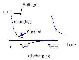
Lets do a capacitor ripple current calculation example based on square AC voltage load – Figure 1.
where,
Tperiod = is the time period = 1/f of the AC load (for example 5us for f=200kHz)
Tload is the charging time, in case of symetrical signals it is 0.5 of Tperiod (= 50% duty cycle)
Capacitor is charging during voltage applied until Tload time. For the rest of the period the current is drawn out of the capacitor. The charge drawn from the capacitor during the discharge period, must equal the charge added during the charge period. Therefore the discharging current during the load period must equal:

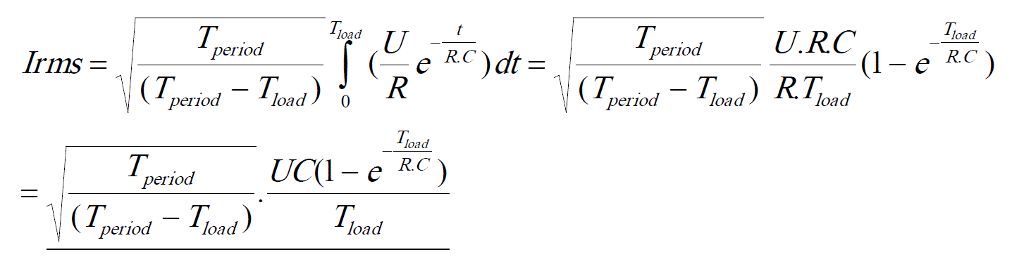
total ripple current is expressed by:
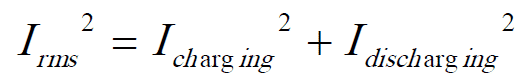
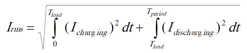
regarding to [1]:

Charging current of capacitor with leakage current negligible comparing to charging current is defined by equation:

where,
U – applied voltage
R – total circuit resistance ( = series resistance + Capacitor’s ESR)
t – time
tau – time constant = R.C
C – capacitance
Ripple current Irms can be then expressed by [4] and [5]::
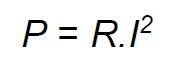
Power equation is defined:
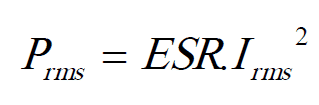
The dissipation power by capacitor us than:
In practice, we may have various AC load patterns applied to capacitors and it may be easier to check the real operation / worst case load to the capacitor by oscilloscope and maximum dissipated power by infrared camera:
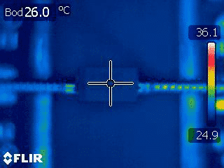

The maximum self-heating of the capacitor shall not exceed manufacturers’ specification. The figure 3. illustrates tantalum capacitor under full load with temperature rise of almost 10C compare to ambient, no load conditions (Figure 2.). The temperature rise is still below maximum self-heating specified by the manufacture and thus suitable for continuous operation.
Practical layout and thermal considerations
In real designs, ripple current capability is not determined by the capacitor alone but by its thermal environment on the PCB. To minimize self‑heating, it is recommended to place high‑ripple capacitors on wide copper areas, with multiple vias to internal and bottom planes, so the copper acts as an efficient heat spreader. Locating these capacitors away from hot components such as power MOSFETs, rectifiers, or magnetic cores further reduces local ambient temperature and improves lifetime. When several capacitors are used in parallel, proper routing and symmetric placement help to equalize current sharing, avoiding overload of a single part and lowering the effective RMS current per component.
passive-components
Choosing the Right Capacitor to Reduce the Ripple Voltage Amplitude
To choose the right capacitor for the input filter of a switching regulator, for example, the capacitance needed to achieve a desired voltage ripple can be calculated, if the operating conditions of the regulator are known. When the capacitance is calculated, a candidate component can be identified, and the ripple current determined from the known ESR. This ripple current must be within the capacitor’s ripple current handling capability, if the device is to be suitable for use. This is where selection can become difficult, because both ESR and capacitance are known to vary with temperature, operating frequency, and the applied DC bias (in case of MLCC class II capacitors).
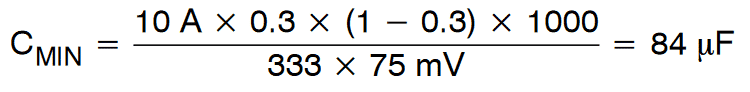
The capacitance can be calculated using the equation (ref.TI Application Report SLTA055):

where
fSW is the switching frequency in kHz
IOUT is the steady state output load current
CMIN is the minimum required ceramic input capacitance in μF
VP(max) is the maximum allowed peak-peak ripple voltage
dc is the duty cycle (as defined above)
Example Capacitor Calculation:
Given:
- VIN = 12 V
- VOUT = 3.3 V
- IOUT = 10 A
- η = 90%
- fSW = 333 kHz
- dc = 0.3
- max ripple voltage allowed = 75mVpp
The minimum capacitance required to reduce the ripple voltage to 75 mVpp is calculated to be:
Capacitor ripple current requirements:
conversion from Vpp to Vrms requirements follow equation: Vrms = 1/ (2 ×√3) × Vpp [11]
in our case, base on [11] above 75 mVpp ~ 22 mVrms
Ohm’s law can be used then to determine rms ripple current requirements. If the selected capacitor ESR specification = 35 mΩ, ESR input bulk capacitor, the ripple current capacitor requirements are: 22mV / 35 mOhm ~ 628 mA.
It shall be noted that the capacitor’s ESR is frequency and temperature dependent, thus it has to be examined in the full range of operation conditions. For MLCC class II capacitors, the effective capacitance under DC bias can be significantly lower than the nominal value at 0 V. Therefore, when using the above calculation, the selected capacitor or capacitor bank should be verified against the manufacturer’s DC bias curves to ensure that the effective capacitance in the actual operating voltage and temperature conditions still meets or exceeds CMIN.
Simulation and Modelling
Leading capacitor manufacturers provide various simulation, S parameters and modelling tools to evaluate the component behavior with application voltage, temperature and frequency.
Using the online simulation, engineers can quickly analyze and compare multiple capacitors and its suitability for the specific application. Very often the models can be also exported for PSpice tools that enable high fidelity simulation of the complete electrical circuit.
Ripple Current of Capacitor Technologies
Ripple current for ceramic capacitors
Internal heating within ceramic capacitors is a problem that affects the performance of many electronic circuits. In these capacitors, the maximum ripple current is determined by temperature characteristics of the component. The ripple current of ceramic capacitor varies depending on the temperature of operation. Ceramic capacitors operating at higher temperatures have less ripple current capability compared to those operating at lower temperatures. For this reason, this parameter is usually measured at room temperature. The method of measuring ripple current of these components varies from one manufacturer to another. As such, it is critical to understand the method used by a supplier when analyzing ripple current data for different capacitors.
Exceeding the ripple current rating of a ceramic capacitor can significantly affect its performance. Although heating a capacitor beyond the temperature specified by the manufacture may not cause immediate failure, overheating ceramic capacitors accelerates their failure rate. Compared to small footprint components, physically larger ceramic capacitors have higher tolerances to ripple current. The greater thermal mass and volume of larger capacitors enables them to absorb more energy, and it takes more time before their maximum rated temperature is reached.
The coefficients of thermal resistance for ceramic capacitors of a given chip size can be different. This is due to variation in the number of electrode plates. High capacitance components have more electrode plates compared to low capacitance components of same size. Electrode plates act as heat sinks, and capacitors with a higher number of these plates release heat from their ceramic blocks more easily when compared to components of same size but with fewer plates.
Heating in ceramic capacitors can cause thermal gradients. These thermal gradients can cause cracking. To prevent cracking, the maximum temperature rise in ceramic capacitors is usually limited to 50C. Unlike aluminum and tantalum capacitors, ceramic capacitors are not prone to negative ripple voltage pulse problem. This is because ceramic capacitors are non-polar components.
Ripple current for tantalum capacitors
Within a chip tantalum capacitor, heat is generated by DC leakage current and by the AC signal. This heat is lost to the surroundings through a combination of the following heat transfer methods: conduction, convection, and radiation. The rate at which heat is lost to the surroundings depends mainly on the temperature gradient between the component and the ambient temperature. At a specified frequency, the heat generated by ripple current is equal to the product of the square of the rms value of the current and the ESR of the capacitor, I2R. On the other hand, the leakage current generates heat that is equal to the product of the current and the applied voltage.
Most of today’s high performance circuits operate at high switching speeds, high currents, and low voltages that demand very low ESR capacitors. Capacitor manufacturers have been reducing the equivalent series resistance of tantalum capacitors to meet the evolving requirement of electronic circuits. For low-voltage circuits that operate at high currents such as some modern CPUs, the demand for very low ESRs is even higher. Low equivalent series resistance enables capacitors to withstand high ripple currents. In comparison, capacitors with high ESR ratings dissipate more heat, and are unsuitable for high ripple current environments. Since temperature rise in tantalum capacitors is a function of ESR, ripple current flowing through a capacitor, and thermal resistance, reducing ESR helps to improve the ripple current capability of these components.
Electronic circuits that operate at very high clock speeds have higher current requirements compared to those that operate at lower speeds. Circuits operating at such high speeds expose capacitors to large ripple currents, and very low ESR components are required to minimize power dissipation. Excess power dissipation can raise the internal temperature of tantalum capacitors to unacceptable limits. Exposing tantalum capacitors to high temperatures lowers their reliability and increases their susceptibility to failure.
Ripple current for aluminum electrolytic capacitors
Aluminum electrolytic capacitors are used for a broad spectrum of applications including energy storage, smoothing, and filtering applications. Some applications such as smoothing and filtering load electrolytic capacitors with AC ripple current. This ripple current causes power dissipation and heating, and subjecting electrolytic capacitors to high temperatures shortens their life. In addition, high temperatures affect capacitance, aluminum resistivity, electrolyte conductivity, and leakage current of these electrolytic capacitors.
In many electronic circuits, the capacitor is the component that limits the life of the system. As such, it is important to consider all the factors that can accelerate the failure rate of these components when analyzing the overall reliability of a system. For aluminum electrolytic capacitors, the factors that can accelerate failure include extreme temperatures, reverse bias, extreme frequencies, transients and high voltages.
Temperature rise in aluminum electrolytic capacitors is a function of equivalent series resistance, root mean square value of current flowing through a capacitor, and thermal characteristics of a component. The hot spot temperature, temperature at a given spot within a capacitor, is the key factor that determines the operational life of an aluminum electrolytic capacitor. The hot spot temperature is a function of the ambient temperature, thermal resistance, and power loss due to AC current. Inside an aluminum electrolytic capacitor, temperature rise and power loss have a linear relationship. Power loss in electrolytic capacitors is mainly due to voltage changes across the dielectric, leakage current losses, and ohmic resistance losses.
When selecting an electrolytic capacitor for power electronics applications, it is important to select components that are optimized to withstand high ripple currents. Such capacitors are specially designed to operate under severe conditions. The most common way of enhancing the ripple current capability of electrolytic capacitors is by minimizing the equivalent series resistance.
The equivalent series resistance of electrolytic capacitors decreases with an increase in the number of electrodes tabs. Increasing laser-welded tabs enhances ripple current capability, thus reducing internal heating and lengthening the life of a capacitor. In addition, using multiple laser-welded tabs helps to improve vibration and shock resistance of aluminum electrolytic capacitors.
Ripple current for film capacitors
In power electronic circuits, film capacitors are used for a wide range of applications including DC-link and DC output filtering applications. Polypropylene is widely used in the construction of film capacitors. This dielectric material offers low dissipation factor, and has good performance over a wide range of temperatures and frequencies. As compared to aluminum electrolytic capacitors, film capacitors have higher ripple current capacity and voltage capability. The ripple current capacity of these capacitors is about three times that of aluminum electrolytic capacitors. In addition, film capacitors have high tolerance to shock and vibrations.
Film capacitors, compared to conventional electrolytic capacitors, have lower equivalent series resistance. This characteristic enables these capacitors to tolerate higher ripple currents. Furthermore, the ESR of polymer film capacitors is relatively constant over a wide range of temperatures. As in other capacitors, ripple current causes power dissipation in film capacitors. This power dissipation raises the internal temperature of film capacitors, thus reducing their life. The operational life of metallized polymer film capacitors is greatly determined by the core temperature.
How this fits into the overall design flow
This article focuses on the physical mechanisms of ripple current, self‑heating and lifetime, and on the basic calculation of Irms and dissipated power. For detailed limits and test methods, you can refer to the dedicated articles on ripple current ratings, transient and surge load, and ripple current testing listed below. In a typical design flow, engineers first estimate ripple current and power dissipation as described here, then apply the technology‑specific derating and test recommendations from those follow‑up articles to validate the final component choice.
passive-components
Further Read:
- Capacitor Ripple Current, Transient and Surge Power Load Ratings
- Capacitor Ripple Current Testing: A Design Consideration
- Examining the Influence of ESR and Ripple Current on Selecting the Suitable Capacitor
- Why Low ESR Matters in Capacitor Design
Frequently Asked Questions about Ripple Current in Capacitors
Ripple current is the AC component of current flowing through a capacitor in addition to the DC bias. It causes internal heating and power loss, directly influencing capacitor lifetime and reliability.
Ripple current defines how much AC load a capacitor can handle without overheating. Exceeding this limit accelerates degradation, shortens operational life, and reduces system reliability.
Equivalent Series Resistance (ESR) determines how much heat is generated by ripple current. Lower ESR capacitors dissipate less power, tolerate higher ripple currents, and extend component life.
Each technology has trade-offs in ESR, thermal resistance, and reliability. The best technology selection depends to the operating frequency, voltage, operating temperatures etc. In general the lowest ESR capacitors such as multilayer construction types (MLCC) achieves very low ESR and high ripple current at high frequencies over 100kHz, but at low frequencies below 1kHz its ESR and ripple capabilities may be inferior to other types. Check the manufacturers data sheets and simulation models for the best comparison.
How to Calculate and Manage Ripple Current in Capacitors
- Identify operating conditions
Determine input voltage, output voltage, load current, switching frequency, and maximum allowable ripple voltage.
- Calculate required capacitance
Use the regulator’s operating parameters to compute the minimum capacitance needed to keep ripple voltage within limits.
- Estimate ripple current
Convert peak-to-peak ripple voltage to RMS value and apply Ohm’s law with the capacitor’s ESR to determine ripple current.
- Compare with capacitor ratings
Ensure the calculated ripple current is below the manufacturer’s specified ripple current rating for the chosen capacitor. You can also refer to the manufacturers datasheets and simulation tools to get reference values in the operating conditions.
- Validate with measurement
Use an oscilloscope to measure actual ripple current and an infrared camera to check capacitor self-heating under load.
- Optimize capacitor selection
Choose capacitors with low ESR, adequate capacitance, and proven thermal stability to maximize reliability and lifespan.

