







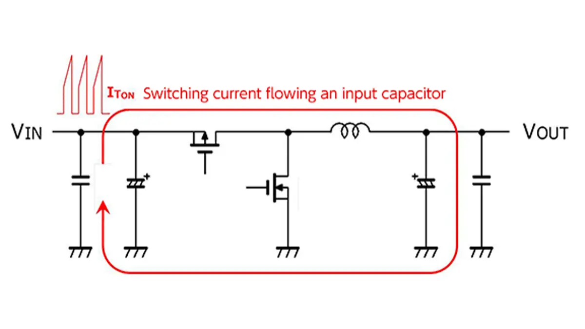
Continuous ripple current, power rating, transient/pulse capabilities etc. are the key parameters to consider for a proper capacitor selection in electric circuit design.
Key Takeaways
- Key parameters for capacitor selection include continuous ripple current, power rating, and transient capabilities.
- High current surge spikes can overload capacitors, especially in low impedance circuits during power ON/OFF.
- Transient loads occur over milliseconds to hundreds of milliseconds, impacting capacitor heating and performance.
- Continuous ripple current is based on the capacitor’s heat dissipation capability and its maximum specified limit.
- Capacitor construction techniques, like thicker electrodes or dielectrics, enhance surge and transient robustness.
Definitions used in this article
- Surge current. Surge current is a very short, high-amplitude current spike that typically occurs during power ON/OFF of a low impedance source, plug-in events, or battery connection. It is usually in the microseconds to tens of microseconds range and follows the lowest impedance path in the circuit and inside the capacitor.
- Transient load. Transient load describes fast but not instantaneous current or voltage changes, typically in the milliseconds to hundreds of milliseconds range. It is characteristic for soft-start sequences, power stage ramp-up, or step-load conditions where Joule heating in real resistive elements of the capacitor becomes significant.
- Continuous ripple current. Continuous ripple current is the steady-state alternating component of the current through the capacitor under normal operation. It is defined over long time intervals, where the capacitor reaches thermal equilibrium, and is limited by its ability to continuously dissipate the generated heat.
- Power load rating. Power load rating expresses the maximum continuous power dissipation that a capacitor construction and case size can handle without exceeding its allowed self-heating and maximum operating temperature. It is directly linked to the specified continuous ripple current rating and the permitted temperature rise, for example 5–10 °C.
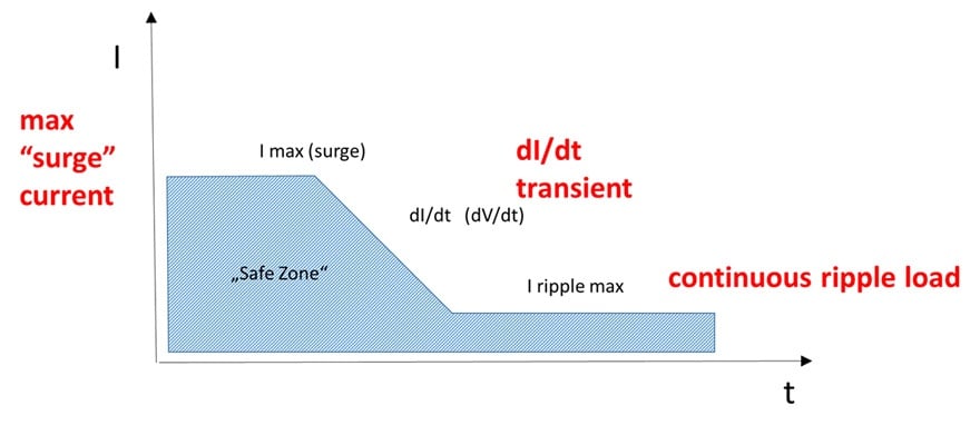
Capacitors are naturally limited by its capability to handle/dissipate ripple current and pulse energy load. The limitation may be significantly different by each capacitor technology, dielectric type, its losses (and its characteristics), but also to a specific construction of the product type individual series. In general, the impact of inrush and ripple current can be divided to three time zones:
- high current immediate surge spike
- transient load dI/dt (dV/dt)
- continuous ripple current/voltage load
The key differentiator is the time domain – how long the current is flowing through the capacitor and how / how quickly / the component can handle / dissipate the heat.
The three main load time domains and their dominant limitations can be summarised as:
- Microseconds – surge spike: Dominated by parasitic inductances and very low impedance paths; the current initially flows mainly in the electrode surface regions due to skin effect. Typical countermeasures are soft-start circuits, series resistance (including NTCs), or dedicated surge-rated capacitors.
- Milliseconds – transient dI/dt: Dominated by internal resistances and the thermal inertia of the capacitor structure; Joule heating in electrodes, terminations and dielectric losses becomes critical. Proper design follows manufacturers’ surge and transient ratings and any specified dI/dt limits.
- Continuous operation – ripple current: Dominated by average power dissipation and long-term temperature rise; the limiting factor is the specified continuous ripple current and associated power rating as a function of ambient temperature.
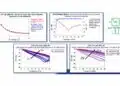
See the following figure illustrating general model of the ripple/inrush current load as function of time.
Capacitor ripple current calculation principles and details are explained also in the following article. This article builds on the fundamental ripple-current concepts discussed there and complements them with a focus on the interaction between surge current, transient load and continuous power rating.
Ripple Current and its Effects on the Performance of Capacitors
High Current Surge Spikes & Transient
The high immediate current spike is a typical short time ‘micro-seconds’ load zone during power switch ON/OFF of a high power, low impedance source circuit. In low impedance circuits, the current spikes can easily reach tenth or hundreds of amperes and it can present an overload risk to the capacitor. Typical example would be a hot plug-in of a low ESR, high capacitance, capacitor directly to automotive 12V battery terminations.
During the “current spike”, high current is flowing through the lowest impedance parts of the capacitor and as this a “high frequency” ripple load type, the current path will flow first mainly through a “surface skin effect“ area of conductive materials. The capacitor dielectric may be then subjected to immediate high electrostatic mechanical pressure force once the electric field on electrodes is created. Depending on duration of the surge spike, Joule heat is generated that has to be absorbed by the capacitor. This is indeed more relevant to the dI/dt transient discussed in the next chapter, but the initial spike may generate some “pre-conditioning” stage of the capacitor and a total energy to be dissipated by the capacitor during the power on sequence has to be considered.
Example of pulse energy consideration
For many film and ceramic capacitors, manufacturers specify an allowable single-pulse energy and, in some cases, a maximum repetition rate. For a pulse that charges the capacitor from 0 to a peak voltage Vpulse, the stored energy is approximately
E ≈ 1/2.C.V2pulse
The resulting pulse energy must remain within the specified limit for the given series, and for repetitive pulses the average power dissipation and cooling conditions of the capacitor have to be considered in addition.
The maximum allowable capacitor’s current shall be specified by manufacturer, however in some cases, the internal resistance of the capacitor is high enough not to allow any dangerous current to flow through the capacitor structure and thus ripple current specification of the part is specified only. It means the capacitor technology is not sensitive to power on load as for example conventional aluminium electrolytic “high ESR” capacitors.
A good circuit design practice is to use soft start circuits, where applicable, to limit the power ON/OFF current load that eliminates most of the immediate current surge load and of course improve overall the hardware design robustness and reliability.
Some capacitor constructions such as tantalum MnO2 capacitors are sensitive to the maximum surge current. Manufacturers and standards (ESA) specify its surge current limits.
Note: “voltage spike” is another phenomenon, however, during voltage spike, the maximum available current can be limited. Typical example of a voltage spike is a low impedance switching between inductor and capacitor that is used in high voltage start-up systems. The risk here is the capacitor electric breakdown when the induced voltage exceeds its breakdown voltage. Sufficient design margin, protective diode or other circuit protection measures may be good idea to implement for robust design of such circuits. In some cases, dangerous “unwanted” low impedance switching can be caused by broken connector/jumper or PCB crack under a vibration conditions – as a tip for uneven capacitor failure identification.
Typical failure modes under surge and transient stress
Improper control of surge, transient and ripple loads does not only reduce capacitor lifetime, but can also lead to sudden and sometimes catastrophic failures. Typical stress-related failure modes include:
Aluminium electrolytic capacitors: Repeated high surge or ripple currents can cause gas generation, vent activation and eventual loss of capacitance or open-circuit behaviour. Elevated ESR and capacitance loss over time are common early indicators of overstress.
Tantalum capacitors: Excessive surge currents or insufficient voltage derating can trigger dielectric breakdown and local overheating, resulting in permanent short-circuits or open circuits. MnO₂ types are especially sensitive and require strict compliance with surge-current specifications.
MLCCs: High surge currents combined with mechanical stress (PCB flex, vibration) can promote micro-cracks in the ceramic body. These may lead to increased leakage or sudden short circuits. Careful layout, derating and mechanical decoupling are essential.
Film capacitors: Self-healing metallised designs can tolerate many small breakdown events, but repeated high-energy pulses gradually erode the metallisation, reducing capacitance and possibly increasing ESR over time. Fully-foiled versions can handle higher currents but require careful size and cooling selection.
Understanding these failure mechanisms and relating them to the discussed time domains helps to define realistic derating, protection measures and inspection criteria in high-reliability designs.
Transient Load dI/dt
In the next transient time domain – approximately in miliseconds to hundrends of milliseconds about range – the current move from the skin surface to the bulk of materials / lower conductive sites of the capacitors and heating of its real resistive elements begin. This Joule heat has to be dissipated by the construction and not to cause any thermal damage to its structure.
This zone is a “usual” operating transient load zone for the capacitors, as most of the power management systems will use soft-start circuits and “shift” the power switch peak from the very short duration of very high current spike (tenth and hundred of amps in microseconds) to this range of typically units of Amps within tenth to hundreds of milliseconds range.
dI/dt (dV/dt) transient power source capability is the key parameter for high power, high voltage circuits using film or ceramic capacitors, thus attention shall be paid for the correct design respecting capacitor manufacturers’ recommendation.
The maximum allowed ripple current and transient load may be very specific to the capacitor type. Some capacitor technologies may define ripple current and maximum surge current only, while dI/dt is considered to be covered by its “maximum surge current limitation”. Thus manufacturer datasheets and technical notes should be followed for details.
Continuous Ripple Current Load
In longer time stamp, after all the transient events are over, the capacitor can be loaded up to its maximum specified continuous ripple current limit. The value is based on the capacitor’s ability to continuously dissipate the heat generated on its resistive elements. These values as a function of ambient operating temperature are usually part of the catalogue or detailed capacitor datasheets.
Continuous ripple current capacitor specification remarks
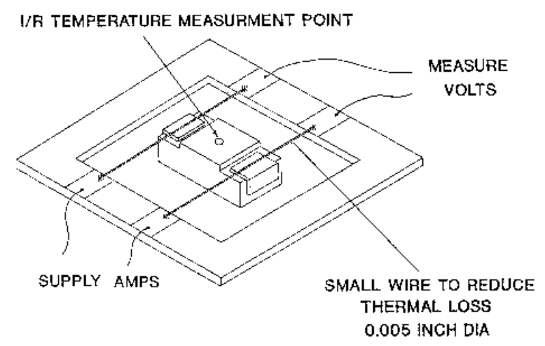
The maximum allowable ripple current is based on the capacitor’s power dissipation capability (as function of construction and case size) and expressed by maximum “self-heating” during the operation under ripple current load condition. The maximum “safe” self-heating value that the capacitor can dissipate continuously without thermal impact to its specified function and reliability can be for example by 10°C. It has to be also noted that the maximum temperature ranking of the part shall not be exceeded. So in our case, if the capacitor’s temperature range is up to 125°C, the 10°C increment, caused by the ripple current self-heating, limits its operation up to 115°C maximum. In often case, the maximum ripple current values at higher ambient temperatures are derated and its values at elevated temperatures can be found directly in the manufacturers’ datasheets.
Practical example of ripple current limit
Ensure the capacitor’s self-heating under your worst-case ripple and transient load does not exceed the specified power dissipation capability. If possible, measure the temperature rise on your PCB in the final hardware, as PCB mounting may significantly improve cooling compared to open-air catalogue values.
In real circuit, the capacitor dissipation capabilities are influenced by more factors such as PCB layout, thermal convection, hardware packaging etc. Therefore, capacitor power dissipation ratio and calculated ripple current load has to be defined at some reference point – “open-air” conditions: Capacitors are connected by sharp termination pins, to minimize thermal conduction, and self-heating temperature under ripple load is monitored by infra-red camera; see example picture on right.
In practical applications, thermal conduction of PCB through terminations are providing much better cooling compare to referenced “open-air” and thus the ripple current rating of the component soldered on PCB is much better compare to the specified catalogue values. In a good thermally balanced PCB the ripple current load can be by rule of thumb up to twice higher compare to its catalogue values. Nevertheless, it is always best to check the self-heating of the part in its worst case load scenario is not exceeding the power dissipation capability of the capacitor type.
Construction of High Power Transient Capacitor Types
There are more ways how capacitor construction can specifically address requirements for higher ripple current and transient load robustness. Such “high power, surge, transient” robust products may be available under a specific series of the capacitor technology.
Here we note two examples of transient pulse ruggedized capacitor designs:
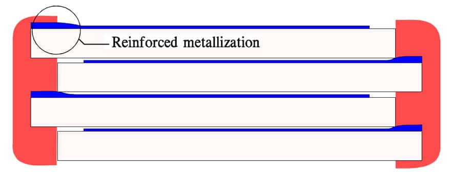
Thicker electrode leads in multilayer capacitor design can be done by reinforced metallization of the electrodes – see figure below on left. This construction will lower resistivity of the electrodes as well as increase its power capability in the transient short time domain when surface skin effect takes place.
This technique is used mostly by organic film capacitors.
Thicker dielectric layer on surface of tantalum capacitor anode – see figure below on right.
Tantalum capacitors are made from a fine sintered tantalum powder and dielectric is then formed elecro-chemically on the tantalum surface. A technology called “shell formation” has been developed by manufacturers to form a thicker dielectric layer on outer surface of the anode that is closest to the cathode system – and thus first hit by surge current.This technology provides higher power ratings and surge robustness against power spikes.
Capacitor technologies and surge robustness
Different capacitor technologies exhibit very different behaviour under surge, transient and continuous ripple current loads. Selection of the appropriate technology for a given application therefore requires understanding not only the capacitance and voltage rating, but also the specific surge and power handling characteristics of each type.
The following table summarises typical tendencies for common capacitor technologies; always refer to the specific series datasheet and application notes for exact limits:
| Capacitor technology | Typical surge behaviour | Continuous ripple capability | Notes for design |
|---|---|---|---|
| Aluminium electrolytic (wet, “high ESR”) | Higher ESR and internal resistance often limit the instantaneous surge current, so only continuous ripple current is specified. Suitable for applications with moderate surge, but still sensitive to repeated high-energy pulses and reverse polarity. | Good ripple capability in power supplies; ripple rating strongly depends on can size, vent design and ambient cooling. | Observe maximum operating temperature and lifetime curves; derate for high ambient temperatures; avoid excessive inrush by using NTCs or soft-start where large bulk capacitances are used. |
| Aluminium polymer | Lower ESR means higher surge current for a given source impedance; some series specify explicit surge and inrush limits. | Excellent ripple current handling thanks to low ESR and good thermal paths; self-heating can still be significant in compact SMD packages. | Carefully check surge/inrush specifications and recommended derating; use controlled ramp-up in high-current rails to avoid overstress. |
| MLCC (ceramic) | Very low ESR and ESL result in high surge and transient currents; sensitive to voltage spikes and mechanical stress. Breakdown may occur if voltage rating and derating are not respected. | Continuous ripple is usually not the primary limiting parameter; rather, voltage, DC bias and thermal effects define permissible operating conditions. | Apply sufficient voltage derating, especially for high-energy pulses; pay attention to PCB layout and mechanical robustness to prevent cracking. |
| Film capacitors | Often available in dedicated pulse and surge-rated series; self-healing metallised films can handle high pulse currents, but repeated pulses cause gradual metallisation erosion. | Very good continuous ripple current capability for suitably sized parts; box and can types are widely used in high-power converters and PFC stages. | Select series specifically designed for pulse and high dI/dt operation; verify allowable peak current, pulse energy and repetition rate in the datasheet. |
| Tantalum MnO₂ | Sensitive to surge and inrush currents; excessive surge or insufficient voltage derating can lead to short-circuit failures. ESA and manufacturer standards define surge current limits and test procedures. | Ripple current capability is moderate and mainly limited by internal heating and maximum case temperature. | Apply conservative voltage derating (for example, 50–60% of rated voltage in high-reliability applications) and respect specified surge and ripple limits; soft-start is strongly recommended. |
| Tantalum polymer | Improved surge and ripple robustness compared to MnO₂ versions, but still requires controlled inrush and voltage derating. | Higher allowable ripple current thanks to lower ESR and better thermal behaviour of the polymer cathode. | Follow manufacturer-specific surge and ripple recommendations; verify that the selected series is qualified for the intended power and transient profile. |
| Supercapacitors (EDLC) | Highly sensitive to overvoltage and large surge currents; low ESR can cause extremely high inrush currents when directly connected to a stiff source. | Designed for high charge/discharge currents, but lifetime depends strongly on temperature and operating voltage. | Always use controlled charging (current limiting) and proper balancing for series connection; respect manufacturer limits for maximum current and cycle life. |
Simulations and Modelling
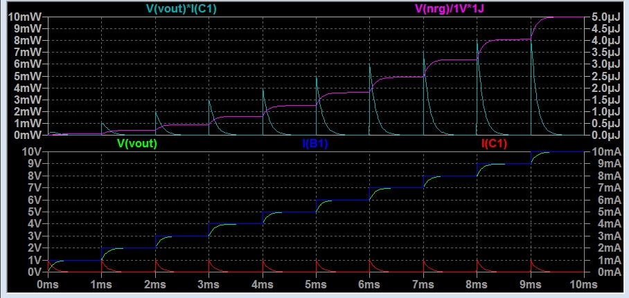
Transient, power ON/OFF simulation and ripple current computer modelling are today a standard tool for electronic design and verification. Use of correct capacitor models may significantly impact relevance and fidelity of PSpice modelling and thus detect potential circuit issues already in the design stage.
Many times, simulation of passive components is not considered as critical parts of PSpice circuit simulation. However, general PSpice software built-in passive components libraries may offer only ideal components model that do not respect its electrical parameters behavior with frequency, temperature or voltage.
Often to see, PSpice simple capacitor equivalent circuit simulations are made from an ideal capacitor, resistor in series in value representing ESR, parallel resistor as DCL and series inductance as ESL MAY NOT be able to realistically simulate the circuit function especially in the transient zone including potential spikes and ripple current load estimations.
Leading manufacturers and PSpice software companies are offering today libraries of passive components including S-parameters of each capacitor part type that can be imported into the simulation to achieve high fidelity of modelling.
FAQ: Capacitor Ripple Current, Transients, and Power Load Ratings
The crucial limiting factors are ripple current, surge (transient) current, and continuous power load. These depend on the capacitor technology, type of dielectric used, construction, and the ability to dissipate heat during operation [1].
Surge current is a high instantaneous current spike, usually occurring during power switch ON/OFF events, especially in low impedance circuits. It can sometimes exceed the capacitor’s safe operational limits and should be managed through proper design or soft-start circuits.
The continuous ripple current rating defines the maximum current a capacitor can handle without exceeding its safe temperature rise. Exceeding this can lead to thermal degradation or failure.
Special construction techniques, like reinforced electrode metallization or thicker dielectric layers (especially shell formation in tantalum types), increase robustness against power surges and improve transient load handling.
For accurate design verification, use high-fidelity capacitor models with relevant S-parameters and data that account for frequency, temperature, and voltage dependencies, rather than relying solely on ideal models.
No. The continuous ripple current rating is defined for steady-state conditions and limited temperature rise, while surge events are short, high-amplitude pulses that may be constrained by different mechanisms. Dedicated surge or pulse ratings and limits, if provided, must be considered in addition to the ripple current specification.
As a practical rule of thumb, it is advisable to keep a few degrees Celsius margin below both the maximum specified self-heating used for the ripple rating and the maximum operating temperature of the capacitor. This helps to accommodate variations in PCB cooling, tolerance of ESR and changes over lifetime.
Whenever the available source can deliver very high instantaneous current (for example, low impedance DC bus, batteries, large DC links) and the capacitor’s surge or inrush rating is close to the expected stress, external current limiting such as NTC thermistors, series resistors, inrush limiters or soft-start circuits should be implemented to ensure robust operation.
How-to: Select a Capacitor for Ripple Current, Transients, and Power Load
- Identify Application Requirements
Assess the surge, transient and continuous ripple current requirements for your circuit, including worst-case power ON/OFF events, soft-start profiles and long-term operating conditions over temperature.
- Check Manufacturer Datasheets
Review the maximum allowable ripple current and transient ratings from the capacitor datasheets, paying attention to derating recommendations for high temperatures.
- Consider Soft-Start and Protection Measures
Implement soft-start circuits or surge limiting components to minimize harmful current spikes during power ON/OFF cycles.
- Choose Construction for Robustness
Select capacitors with features like thicker electrodes or dielectrics for improved surge and thermal resilience, especially where transient loads are significant.
- Verify Thermal Dissipation
Ensure the capacitor’s self-heating under your worst-case ripple and transient load does not exceed the specified power dissipation capability. If possible, measure the temperature rise on your PCB in the final hardware, as PCB mounting may significantly improve cooling compared to open-air catalogue values.
- Model and Simulate Critical Circuits
Use accurate models in circuit simulation (like PSpice) with proper S-parameters to verify capacitor behavior against real-world loading, especially in transient and ripple regimes.
Further read:
- Ripple Current and its Effects on the Performance of Capacitors
- Capacitor Ripple Current Testing: A Design Consideration
- Examining the Influence of ESR and Ripple Current on Selecting the Suitable Capacitor
- Why Low ESR Matters in Capacitor Design