
A practical capacitor is a non-ideal component. Its circuit model contains series inductance (ESL) and series resistance (ESR). Although equivalent series resistance is often shown in circuit models as a constant value, it varies depending on operating conditions. ESR is resistance from a combination of energy loss mechanisms under specific operating conditions.
Some energy losses within a capacitor can be attributed to the conductors while others involve the dielectric material. These losses vary mainly depending on voltage and temperature. The most common energy loss mechanisms include dielectric losses, ferroelectric losses, dielectric conduction losses, interfacial polarization, partial discharge losses, ohmic resistance losses, sparking between conductors, electromechanical losses, and eddy current losses.
Together with its capacitance value, ESR defines a time constant for charging and discharging of the capacitor and thus how quickly the capacitor react on voltage/current changes/ripple. In practical smoothing applications capacitor technologies are combined in parallel, where high capacitance parts are taking care of bulk filtering (aluminium capacitors or tantalum capacitors) and small MLCC capacitors with low ESR are taking care of fast, high frequency spikes.
Note: Lowest ESR capacitors is not always the best choice. Too low ESR of capacitors in certain applications such as feedback capacitors could eventually cause some issues with the operating amplifier oscillations out of operating conditions. LDO type circuits have been also very sensitive on capacitor ESR range (including shift of ESR with temperature !) and historically tantalum capacitors were strongly recommended to use with LDO instead of MLCCs with too low ESR values. These issues are typical for older generation of ICs, the latest ICs with continuous improvement of design architecture and components are significantly less sensitive to capacitors’ ESR values. However it is always good idea to check the IC chip datasheet.
Energy Loss Mechanisms In Capacitors
Dielectric losses
Different dielectric materials respond differently when voltage is applied or removed. Dielectric losses are associated with how dielectric materials polarize or relax in response to voltage. The magnitude of these losses depends on both temperature and frequency. The dissipation factor (DF) is commonly used to describe the dielectric losses of a material. The dissipation factor and equivalent series resistance of a capacitor are dependent on the electrodes as well as their configurations. In film capacitors, dielectric losses are the main contributor to the overall equivalent series resistance.
Dielectric conduction losses

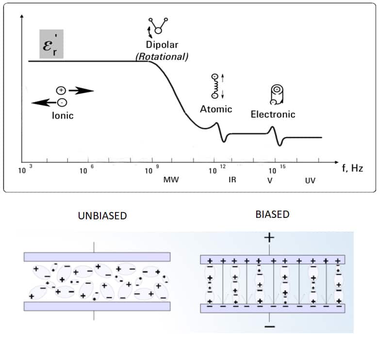
Dielectric conduction losses refer to losses that are caused by the actual movement of charge across a dielectric material. These losses tend to be largest at high temperatures and low frequencies. In some capacitors, such as MLCC class II, dielectric conduction losses are strongly dependent on applied voltage.
Ohmic resistance losses
Metallic terminals, electrodes, and internal wiring of capacitors exhibit resistance. This energy loss does not vary significantly with temperature and frequency. However, at high frequencies, the skin depth effect in electrodes becomes significant. Although ohmic resistance losses occurring within terminals and internal wiring are insignificant in low current applications, they should not be ignored in high current applications.

Ferroelectric hysteresis losses
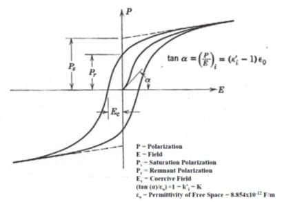
Some high dielectric constant materials exhibit losses that are strongly dependent on applied voltage. These losses are referred to as ferroelectric hysteresis losses, and they occur when the internal polarization field and the applied field have the same magnitude. This condition causes saturation of the dielectric material. Capacitors that have such high dielectric constant materials exhibit sensitivity to voltage reversals, permanent polarization, and variation of capacitance with voltage. Ferroelectric hysteresis losses are common in ceramic capacitors with high dielectric constant materials.
Interfacial polarization losses
The dielectric systems of most high voltage capacitors have at least two different materials. Each of these materials has different permittivity and conduction properties. This difference in properties causes accumulation of charge at the internal interfaces of such materials when a DC voltage is applied. Interfacial polarization losses are common in low-frequency high voltage capacitors.
Partial discharge losses
Some capacitors exhibit partial discharges when they are exposed to high rates of voltage change. This energy loss mechanism is referred to as partial discharge loss, and it is common in gas filled capacitors and liquid-filled capacitors, most notably at high voltages. Partial discharge losses can also be caused by voltage reversals.
Eddy currents
In capacitors, eddy current losses are strongly dependent on frequency. In most applications, this energy loss mechanism has an insignificant effect, and it is usually ignored. However, in pulse forming networks, eddy current losses have a significant effect and should be considered.
Sparking
In some capacitors, sparking can occur during discharge.Sparking occurs mainly between adjacent metallic surfaces, and it is a common energy loss mechanism in pulse capacitors. This energy loss mechanism is dependent on both voltage and frequency.
Electromechanical losses
In most capacitors, electromechanical losses occur mainly within the dielectric material and the internal wiring. In the dielectric material, electromechanical losses are primarily caused by electrostriction. In some cases, it may be caused by piezoelectric effect. In internal wiring, Lorentz forces can cause flexing. When this happens, it leads to energy losses.
ESR in Ceramic Capacitors
Equivalent series resistance is one of the most important parameters to consider when selecting a ceramic capacitor for your electronic circuit. In ceramic capacitors, this parameter is a summation of losses occurring within the metallic elements and dielectric material. Many applications demand ceramic capacitors with low ESR. As such, it is critical to consider this parameter when selecting a ceramic capacitor for your circuit.
The dielectric losses in ceramic capacitors mainly depend on microstructural factors, dielectric formulation, and concentration of impurities. Porosity, morphology, and grain size are the main microstructural factors that determine the equivalent series resistance. The loss factor varies from one dielectric material to another. Excess losses can cause the dielectric to heat leading to thermal breakdown and capacitor failure. In ceramic capacitors, dielectric losses are predominant at low frequencies. At high frequencies, these losses diminish and their contribution to the overall ESR is negligible.
Metal losses comprise of ohmic resistance losses and skin effect. In ceramic capacitors, metal losses mainly depend on the characteristics of the materials and construction. Skin effect is a common energy loss mechanism in electrodes and terminations of ceramic capacitors. This energy loss mechanism is frequency-dependent. Excessive metal losses can cause heating and thermal breakdown in ceramic capacitors. Unlike dielectric losses, metal losses are predominant at high frequencies.
High ESR values can lead to excessive power loss and shortened battery life. Using low loss capacitors in coupling and bypassing applications helps to extend the battery life of portable electronic devices. In RF power amplifiers, it is easy to attain high efficiency and increased power output with low loss ceramic capacitors. Use of high ESR capacitors lowers the efficiency because a large percentage of power is wasted in form of ESR loss.
Low loss capacitors dissipate less heat. Use of such components enables circuit designers to manage thermal issues in electronic circuits. In high RF applications, use of high ESR ceramic capacitors can lead to excessive heating. In low noise amplifiers, low ESR capacitors are used to increase efficiency and effective gain.
Class 1 ceramic dielectrics have excellent stability and low dissipation up to very high frequencies. They are commonly used in applications that demand low loss capacitors. On the other hand, Class 2 ceramic dielectrics have higher losses but offer high capacitance/volume efficiencies.
ESR in Tantalum Capacitors
The anode of tantalum capacitors is made of tantalum metal powder sintered particles. However, foil style tantalum capacitors (not so commonly used anymore) use a strip of a foil. A layer of oxide is used as the insulator, and its thickness determines the voltage rating of the capacitor. Manganese dioxide or conductive polymer are the second conductor in solid tantalum capacitors used to cover the oxide layer. In the case of foil style capacitors, the electrolyte is the second conductor. In both solid tantalum and foil style capacitors, additional materials are used to make terminations.
In tantalum capacitors, the main contributors of equivalent series resistance are losses in the contacting materials and oxide insulators. At high frequencies, oxide insulator losses are less significant as compared to contact material losses. However, at low frequencies, oxide insulator losses are more significant.
Oxide losses in tantalum capacitors increase slightly with an increase in temperature. In comparison, the resistance of manganese dioxide decreases with an increase in temperature. Furthermore, manganese dioxide resistance losses vary depending on manufacturing procedures, and they are complex to analyze. Conductive polymer tantalum are featuring lower ohmic resistance losses – lower ESR – compare to MnO2 conventional types and it has practically no change of ESR with temperature unlike MnO2 where ESR at negative temperatures can be around 10x higher compare to those polymers.
At low frequencies, notably below 1 Hz, dielectric absorption and leakage current have a significant effect and should be considered. Generally, in a typical tantalum capacitor, ESR decreases with an increase in frequency. ESR affects the performance of tantalum capacitors in many ways. To start with, its resistive effect causes heating in capacitors. Secondly, ESR increases impedance in circuits, thereby making tantalum capacitors less effective for decoupling and filtering applications.
ESR in Aluminum Electrolytic Capacitors
For medium and high voltage applications, low loss aluminum electrolytic capacitors are required. Low ESR capacitors have less power losses and internal heating problems as compared to high ESR capacitors. Apart from lowering performance, high ESR values reduce the life of an aluminum electrolytic capacitor. In addition, a low ESR value allows a greater ripple current capacity to be achieved.
In an aluminum electrolytic capacitor, the aluminum anode, cathode foils, electrolyte, and tabs contribute to the overall ESR of the capacitor. The value of resistance from each source mainly depends on frequency and temperature. At low frequencies and low temperatures, the aluminum oxide makes the largest contribution to the overall ESR. On the other hand, at high frequencies and high temperatures, the largest contribution to the overall ESR comes from the electrolyte. Generally, under application conditions, paper combinations and the electrolyte are the primary sources of equivalent series resistance in these capacitors.
Polymer and hybrid (combining polymer and wet electrolyte) electrodes with significantly lower and more stable ESR are available on the market as well, that address most of the disadvantages of the wet electrolytic capacitors reducing the ohmic losses, dry out effect (reliability and stability improvement) and ESR temperature dependency.
The ESR value of an aluminum electrolytic capacitor is dependent on thickness and density of paper separators. To minimize equivalent series resistance, thicker and denser separators are not recommended.Use of many tabs and high conductivity electrolyte material helps to reduce ESR in aluminum electrolytic capacitors. The tab connections, foils, and paper separators can be tailored to produce a specific resistance contribution to the overall equivalent series resistance.
ESR with frequency capacitor technologies comparison

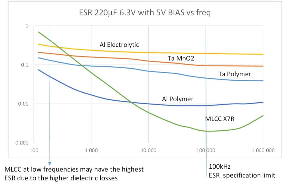
ESR is used to characterize capacitors losses mainly in higher frequency domain with standard reference frequency at 100kHz. ESR with frequency chart is illustrating losses in the entire frequency spectrum. As discussed above, the low frequency losses below around 1kHz are driven by “slower” polarization and losses in dielectric layers, mid frequencies (~ 1kHz to 10kHz) are driven by internal construction losses (such as conductivity of internal structure and electrolyte), the high frequencies >100kHz are driven by mostly ohmic losses of terminations, contacts etc.
Referring to Fig.3. MLCC capacitors are exhibiting lowest ESR values compare to other technologies referred to a standard specification frequency 100kHz thanks to its multilayer structure. This is a beneficial for smoothing of higher frequencies and fast spikes for applications such as switching power supplies. However, at low frequencies, MLCC class II capacitors are featuring higher ESR(and DF) compare to other technologies. Thus in practical example in case of low frequency spike present (such as 50-216Hz often seen) it is more efficient to use the MLCCs in parallel with some aluminium or tantalum electrolytic capacitors.
Conclusion
Just like other physical devices, capacitors are not perfect or ideal components. The materials that are used to construct capacitors have finite electrical resistances. As such, capacitors contribute some resistance to a circuit. The real part of the complex impedance, equivalent series resistance, is a sum of energy loss mechanisms that occur in a capacitor. These small losses can become significant when the device is made to operate under certain conditions.
Some of the conditions that can significantly affect the behavior of a capacitor include high current, high frequency, and extreme temperatures. Whereas frequency, voltage, and temperature can affect the performance of a capacitor, only frequency affects ESR. When designing a circuit, it is, therefore, critical for the design engineer to consider the frequency of operation of the circuit as well as the temperature of the components.
Further Read:
- Examining the Influence of ESR and Ripple Current on Selecting the Suitable Capacitor
- Ripple Current and its Effects on the Performance of Capacitors
Key Takeaways
- Low ESR capacitors reduce energy losses, improving performance and extending battery life in circuits.
- The equivalent series resistance (ESR) changes with temperature, voltage, and frequency, impacting capacitor efficiency.
- Different types of capacitors, like tantalum and aluminum electrolytic, have unique ESR behaviors that affect their applications.
- In high-frequency applications, MLCC capacitors demonstrate the lowest ESR but perform differently at low frequencies compared to aluminum capacitors.
- Understanding ESR is crucial for circuit design, especially under varying conditions like high current and extreme temperatures.
Frequently Asked Questions about Low ESR in Capacitor Design
ESR (Equivalent Series Resistance) is the resistive component of a capacitor that represents energy losses due to dielectric, conductor, and interface effects. It varies with frequency, voltage, and temperature, and directly impacts capacitor efficiency and thermal stability.
Low ESR capacitors reduce power losses, minimize heating, and improve efficiency in high-frequency and high-current applications. They are essential in RF amplifiers, low-noise amplifiers, and power supply filtering where stable performance is required.
Yes. In some circuits, such as older LDO regulators or op-amp feedback loops, excessively low ESR can cause oscillations or instability. Designers should always check the IC datasheet for recommended ESR ranges.
MLCCs (Multilayer Ceramic Capacitors) generally provide the lowest ESR at high frequencies, while polymer tantalum and hybrid aluminum electrolytics offer stable ESR across temperature ranges and higher capacitance values.
How to Select the Right Capacitor with Low ESR
- Define your application requirements
Identify whether the capacitor will be used for filtering, decoupling, RF amplification, or power supply stabilization. Each use case has different ESR tolerance needs.
- Check frequency and temperature conditions
Evaluate the operating frequency and temperature range. ESR decreases with frequency but may increase with temperature depending on the capacitor type.
- Compare capacitor technologies
Use MLCCs for high-frequency, low-loss applications. Choose polymer tantalum or hybrid aluminum electrolytics for stable ESR and higher capacitance in power circuits.
- Validate with datasheets
Always confirm ESR specifications in the manufacturer’s datasheet to ensure compatibility with ICs and circuit stability requirements.
- Test in real conditions
Prototype and measure ESR under actual load, ripple current, and thermal conditions to verify long-term reliability and efficiency.

