This article walks through the current state of Vishay’s non-linear resistor (NLR) simulation toolkit and explains what it means for engineers who need to go beyond derating margins and bench testing.
For most of SPICE’s 30-plus-year history, passive components — and non-linear resistors in particular — have been the simulation blind spot of circuit design. Vishay Intertechnology has spent more than a decade systematically closing that gap for NTC thermistors, PTC inrush current limiters, voltage-dependent resistors (VDRs), and now polymeric PTC (PPTC) resettable fuses.
Why Non-Linear Resistors Have Been Hard to Simulate
Unlike semiconductor vendors, passive component manufacturers have historically published only static datasheets rather than SPICE models. The underlying assumption has been that engineers would rely on conservative derating rules and safety margins — confirming performance only on physical prototypes. For components whose resistance changes non-linearly with temperature, voltage, or current (such as NTC thermistors, ceramic PTCs, VDRs, and resettable PPTC fuses), this limitation is meaningful: the interactions between thermal mass, tolerance stack-up, self-heating, and ambient conditions are difficult to reason about analytically and time-consuming to sweep manually.
Mike Engelhardt, the original author of LTspice and developer of the newer QSPICE tool, has noted that SPICE simulation is primarily valuable for developing designer intuition rather than verifying final performance — a point equally valid for passive component models. Good models must capture thermal effects and manufacturing tolerances to be genuinely useful, not just reproduce a nominal resistance curve.
The Vishay NLR Simulation Toolkit
Starting in 2014, Vishay has progressively built what it calls its Electronic Simulation Toolkit for Non-Linear Resistors — a freely available collection of models, application circuits, and reference documents. The central reference document (Vishay document 29235) covers the full scope: how to build a Berkeley NTC SPICE model from scratch when a ready-made file is not available, how to use temperature as an external voltage source to drive the thermistor in a dynamic simulation, and how to model the thermal inertia of the surrounding medium with an R-C network.
The toolkit spans multiple simulation platforms: LTspice (now offered by Analog Devices), Simetrix, Multisim, PartQuest Explore, and the more recently supported QSPICE from Qorvo. Each platform receives adapted model files, since SPICE syntax and parametric sweep capabilities differ between tools.
Covered application areas include:
- Temperature sensing and compensation — NTC voltage dividers, Wheatstone bridge circuits for strain-gauge temperature compensation
- On/off and PID temperature control — models combining Vishay NTC thermistors, opto-triacs, and optocouplers
- Peltier cooler control — thermal management circuits with active cooling elements
- Fire and level detection — level-detection and rate-of-rise fire alarm circuits using NTC sensors
- Inrush current limitation — PTC and NTC-based precharge networks for automotive and industrial power stages
- Overvoltage protection — VDR and multilayer varistor (MLV) circuit sections (document 29235, section 14)
- LED current mitigation — thermally compensated LED drive circuits
A companion webinar series — Vishay Thermistors Electronic Simulation — provides three recorded sessions: the first demonstrates live application circuits; the second focuses on QSPICE-based workflows; and the third covers integration with MATLAB Simulink/Simscape for multi-domain physical system simulation.
NTC Thermistor Models: Key Capabilities
The classical SPICE model of an NTC thermistor uses SPICE’s built-in TEMP variable to sweep ambient temperature — useful for examining the general static response of a sensor divider or temperature compensation network. Vishay has extended this significantly in two directions.
Voltage-driven temperature input
A third virtual pin on the model accepts an externally generated voltage representing temperature. This allows the NTC’s input temperature to be produced by the circuit itself — for example by integrating heat from nearby power dissipation — and fed back via an R-C network representing the thermal time constant of the surrounding medium. The same fundamental circuit has been validated across six different electronic simulators, with syntax adapted for each.
Tolerance and self-heating integration
Vishay’s models include manufacturing tolerance parameters (for example, ±5% on R25 and ±1% on the B-constant) which can be swept in a Monte Carlo analysis. Self-heating — the temperature rise caused by measurement current — is included in the model formulation. A practical example uses a Vishay NTCLE350 thermistor (PEEK-insulated, leaded, 30 kΩ ±1%) in an oil temperature sensing application from +50°C to +185°C, simulated in LTspice with a Steinhart–Hart coefficient set extracted from the NTCLE317E4103SBA datasheet.
PTC and NTC Inrush Current Limiters in Simulation
The integration of Ametherm — a specialist NTC inrush current limiter brand — into Vishay expanded the simulation toolkit into high-current power applications. NTC inrush current limiters are thermally self-resetting devices placed in series with the AC input of power converters: at startup they present a high impedance that limits the peak inrush current, then warm up during normal operation to a low steady-state resistance. The applications now covered by Vishay’s QSPICE models include:
- Motor drives and variable-speed drives
- Welding equipment and arc-starting supplies
- AC-DC battery chargers and on-board vehicle chargers
- Industrial automation systems
- SMPS front-end stages
The application note (Vishay document 24291) demonstrates how to build a QSPICE behavioural model of a Vishay Ametherm inrush current limiter, extract thermal parameters from the datasheet, and validate simulation results against the published characteristic curves. For ceramic PTC inrush limiters, sections 4.1 and 4.2 of document 29235 address PTCEL-series networks in automotive precharge circuits, including derating as a function of variable ambient temperatures.
QSPICE and the Digital Simulation Frontier
QSPICE — developed by Qorvo and offered free of charge — natively supports Verilog and C++ behavioural blocks alongside conventional analog SPICE netlists, enabling mixed-signal digital and analog co-simulation in a single environment. It can also sweep up to six parameters simultaneously in a single run, which is otherwise not generally supported by commercial SPICE tools.
Vishay’s application note (document 29237) demonstrates how a Verilog module can implement a PID temperature controller while the analog section uses a Vishay NTC thermistor model with full tolerance sweeping, driving a Qorvo SiC transistor output stage or an opto-triac — directly relevant to battery management systems, precision lab instruments, and industrial process controllers.
PPTC Resettable Fuse Models: A New Addition
Polymeric PTC (PPTC) devices — commonly marketed as Polyfuse or resettable fuses — are conductive-polymer-based overcurrent protectors. Under normal conditions their resistance is low (a few milliohms to a few ohms); under a fault current, self-heating causes the polymer to undergo a phase change that dramatically increases resistance, limiting the current. When power is removed and the device cools, it resets to its low-resistance state.
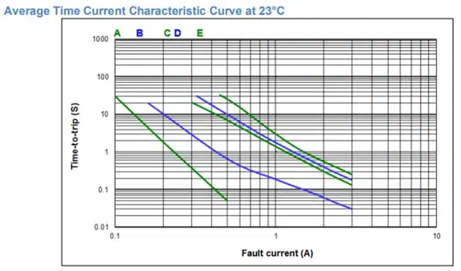
Accurate SPICE models for PPTCs are rare commercially because these devices combine wide tolerances (typically ±50% on resistance at room temperature) with pronounced post-trip hysteresis. Furthermore, most manufacturers provide limited thermal data on their devices. For example, the Bel Power 0ZAF-series datasheet includes only a graph — reproduced here as Figure 1 — showing the device’s response time, or “time to trip,” under fault current conditions.
Vishay has successfully developed a SPICE model capable of accurately reproducing the characteristic curves shown in Figure 1, within a practical margin of approximation. The model captures both switching and non-switching current behaviours, and allows users to define adjustable tolerances — typically ±50% on resistance at low temperatures (around 23°C). To account for the hysteresis observed after switching, the upper tolerance can be extended, for example, to +60%. A simplified schematic of the model is shown in Figure 2.
The PPTC thermal model is structured as a three-stage Cauer network comprising four thermal nodes: T_PPTC (temperature of the internal active polymer material), T_electrode (temperature at the component electrodes), T_PCB (temperature at the PCB solder joint), and T_ambient (far-field ambient temperature). Three pairs of thermal resistance and capacitance (Rth1/Cth1, Rth2/Cth2, Rth3/Cth3) model the thermal impedances between these nodes.
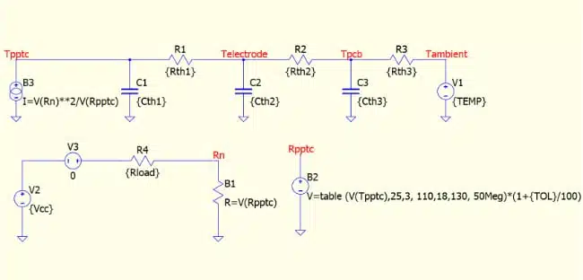
In Figure 2, I(V3) represents the datasheet fault current, and TEMP is the ambient temperature which, after sweeping, shows the corresponding derating. The relationship between resistance and temperature is captured by the behavioural voltage source B2 — a parameter often absent from datasheets. The thermal parameter sextet (Rth1, Cth1, Rth2, Cth2, Rth3, Cth3) is adjusted to align simulation results with the datasheet trip time. Once complete, sweeping the TOL parameter (applied to Rpptc) produces the upper and lower limit curves.
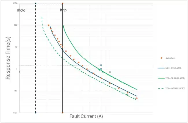
While sweeping six parameters simultaneously is not typically supported by conventional SPICE programs, QSPICE does support this capability. The initial optimisation results, shown in Figure 3, demonstrate a strong correlation with the datasheet values.
This model approach, while developed for Vishay’s own PPTC range, establishes a methodology applicable to any PPTC device for which sufficient thermal data can be extracted from the datasheet. The SPICE-ification of passive components such as PTC and NTC thermistors is a long process — but with continued efforts from manufacturers like Vishay and growing demand from the engineering community, it is steadily advancing and may in the future become a seamless part of component delivery.
Typical Applications
| Component type | Key simulation use case |
| NTC thermistor (sensing) | Temperature sensor linearisation, PID loop design, fire alarm detection |
| NTC thermistor (inrush limiter) | SMPS precharge, motor drive startup, EV charger inrush |
| Ceramic PTC (inrush limiter) | Automotive battery precharge, derating vs. ambient analysis |
| VDR / MLV | Overvoltage clamping, transient suppression margin analysis |
| PPTC resettable fuse | USB port protection, battery pack overcurrent, tolerance/hysteresis analysis |
Design-In Notes for Engineers
- Start with the toolkit document (29235) before modelling from scratch. If a ready-made model for the specific part number is not available, section 6.3 explains how to construct a Berkeley-format NTC model using the B-constant and Steinhart–Hart coefficients from the datasheet. The voltage-driven temperature approach (third virtual pin) is more versatile than the classical TEMP-sweep approach for dynamic thermal simulations.
- Choose your simulator platform based on what the rest of your design uses. All six supported platforms — LTspice, Simetrix, Multisim, PartQuest Explore, QSPICE, and Simulink/Simscape — can run the same fundamental Vishay thermistor models, but QSPICE has advantages for mixed digital-analog simulations and wide parameter sweeps.
- For inrush limiter sizing, always include ambient temperature derating. The steady-state resistance of an NTC inrush limiter depends on the balance between self-heating and heat dissipation to the ambient. The QSPICE models for Vishay Ametherm ICL parts allow ambient temperature to be swept alongside current load to map this derating surface.
- For PPTCs, treat the tolerance band and hysteresis as design variables, not worst-case corners. The Vishay PPTC model explicitly supports tolerance sweeping — use it to confirm that your hold current stays comfortably below the lower trip-current limit across the operating temperature range, including the post-trip elevated-resistance state.
- Request models directly if the part number is not in the library. Application notes and simulation files are available from the Vishay document library using the document numbers referenced in this article.
Learn more
- NTC/PTC Thermistors LTSpice Simulation – Vishay Video Part I
- PTC Current Limiting Protection Device Design With LTspice
- Vishay NTC Thermistor LTspice Simulation for PID Optimization
- NTC Thermistor in Fire Alarm Application – LTSpice Simulation
- Vishay Thermistors Modelling with Simulink Simscape
- Thermistor-Based Temperature Sensing System Explained
- Thermistors Basics, NTC and PTC Thermistors
- Passive Component Models May Have a Significant Impact to Overall Simulation Success
Source
This article is based on a technical paper by Alain Stas of Vishay Intertechnology, titled Vishay’s SPICE-ification of Non-Linear Resistors: Yesterday, Today, and Into Tomorrow, published by Vishay as a manufacturer press release and reproduced with permission. Specifications, model descriptions, thermal network topologies, figures, and application examples are taken directly from this source and the associated Vishay application documents listed below. No specifications have been independently modified or inferred.
References
- Vishay press release / technical paper – SPICE-ification of Non-Linear Resistors
- Vishay Electronic Simulation Toolkit for Non-Linear Resistors – document 29235
- Vishay Thermistors Electronic Simulation webinar series
- Multi-Simulator NTC Thermistor SPICE Model With Temperature Driven by a Voltage – Academia
- SPICE-ify Your Vishay Ametherm Inrush Current Limiters With QSPICE from Qorvo – document 24291
- Digital Simulation of Temperature Control Circuits With QSPICE and Vishay Thermistors – document 29237
- Vishay NTC Thermistors Design Support Tool
- Vishay PPTC Resettable Fuses – product overview on Mouser
- Bel Power 0ZAF-series PPTC datasheet (referenced for model validation)