Passive Components Blog
No Result
View All Result
  • Home
  • NewsFilter
    • All
    • Aerospace & Defence
    • Antenna
    • Applications
    • Automotive
    • Capacitors
    • Circuit Protection Devices
    • electro-mechanical news
    • Filters
    • Fuses
    • Inductors
    • Industrial
    • Integrated Passives
    • inter-connect news
    • Market & Supply Chain
    • Market Insights
    • Medical
    • Modelling and Simulation
    • New Materials & Supply
    • New Technologies
    • Non-linear Passives
    • Oscillators
    • Passive Sensors News
    • Resistors
    • RF & Microwave
    • Telecommunication
    • Weekly Digest

    Microhardness — the Hidden Key to Understanding MnOx Cathode Quality in Tantalum Capacitors

    Samsung to Invest in its Philippine MLCC Facility to Meet Automotive Demand

    Lightweight Model for MLCC Appearance Defect Detection

    DMASS Reports First Positive Signs of European Distribution Market in Q3/25

    TAIYO YUDEN Releases 22uF MLCC in 0402 Size for AI Servers

    Wk 44 Electronics Supply Chain Digest

    Bourns Releases High Current Metal Alloy-based, Multilayer Power Chip Inductors

    Smiths Interconnect Extends Space-Qualified, High-Reliability Fixed Chip Attenuators 

    Samtec Expands Offering of Slim, High-Density HD Array Connectors

    Trending Tags

    • Ripple Current
    • RF
    • Leakage Current
    • Tantalum vs Ceramic
    • Snubber
    • Low ESR
    • Feedthrough
    • Derating
    • Dielectric Constant
    • New Products
    • Market Reports
  • VideoFilter
    • All
    • Antenna videos
    • Capacitor videos
    • Circuit Protection Video
    • Filter videos
    • Fuse videos
    • Inductor videos
    • Inter-Connect Video
    • Non-linear passives videos
    • Oscillator videos
    • Passive sensors videos
    • Resistor videos

    Common Mode Chokes Selection for RF Circuits in Next-Generation Communication Systems

    Capacitor Self-balancing in a Flying-Capacitor Buck Converter

    How to Select Ferrite Bead for Filtering in Buck Boost Converter

    Power Inductors Future: Minimal Losses and Compact Designs

    Percolation Phenomenon: Degradation of Molded Power Inductors in DC/DC Converters

    Connector PCB Design Challenges

    Efficient Power Converters: Duty Cycle vs Conduction Losses

    Ripple Steering in Coupled Inductors: SEPIC Case

    SEPIC Converter with Coupled and Uncoupled Inductors

    Trending Tags

    • Capacitors explained
    • Inductors explained
    • Resistors explained
    • Filters explained
    • Application Video Guidelines
    • EMC
    • New Products
    • Ripple Current
    • Simulation
    • Tantalum vs Ceramic
  • Knowledge Blog
  • Suppliers
    • Who is Who
  • PCNS
    • PCNS 2025
    • PCNS 2023
    • PCNS 2021
    • PCNS 2019
    • PCNS 2017
  • Events
No Result
View All Result
Passive Components Blog
No Result
View All Result

Transformer Topologies in Power Converters

15.2.2023
Reading Time: 7 mins read
A A

This Frenetic blog article from Pablo Blázques provides introduction to the basic transformer topologies in power converters and its key features.

Usually, in all the transformer topologies, we have an input filter (inductance before the primary side of our transformer), the transformer itself and the output filter. Then, depending on the converter topology, we will have different magnetic components in our design.

RelatedPosts

Power Inductors Future: Minimal Losses and Compact Designs

Common Mistakes in Flyback Transformer Specs

Percolation Phenomenon and Reliability of Molded Power Inductors in DC/DC converters

Magnetic components

The main functionalities of magnetics in power converters are energy storage, filtering and galvanic isolation voltage/current. These functions are carried out by the inductors and transformers in the power converters. 

Inductors

Let’s start with the inductors! Their main functionalities are electrical energy storage, adaptation of the converter input and output sources and phase control of power flow through HF resonant LC stage. 

Input filter

Input inductors are wound components that generate a magnetic field to control the current changes. In case of a sudden current increase, an electromotive force is applied against the current in order to control it. While, if the current suddenly decreases, an electromotive force is applied in the same direction as the current.

Output filter

Output filters are used to remove unwanted signals at the output of our analog and digital circuits. Electrical disturbances, both man-made and natural, can affect the performance of our circuit. There are several possible configurations, and the one we chose usually depends on our insertion loss performance.

Transformer

A transformer is defined as a passive component that transfers electrical energy from one circuit to another using electromagnetic induction. The transformer has an influence on the reactive components of the power converter, therefore affecting their performance and size.

Leakage inductance

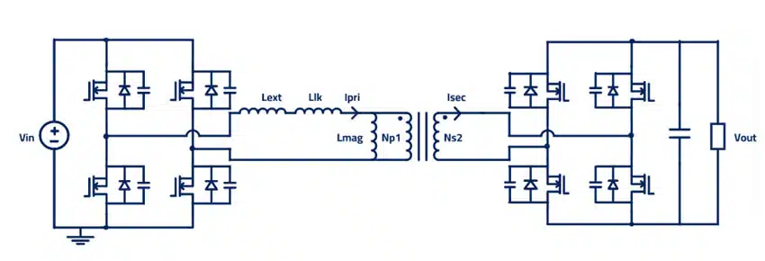
The leakage inductance is an inductive component that results from the imperfect coupling of the primary and secondary windings. It is represented as an inductance on the primary side, and it is positioned in series with the input inductance.

Magnetic Components in Transformer Topologies 

Phase-Shifted Full-Bridge (PSFB): Secondary full wave rectifier and center tap

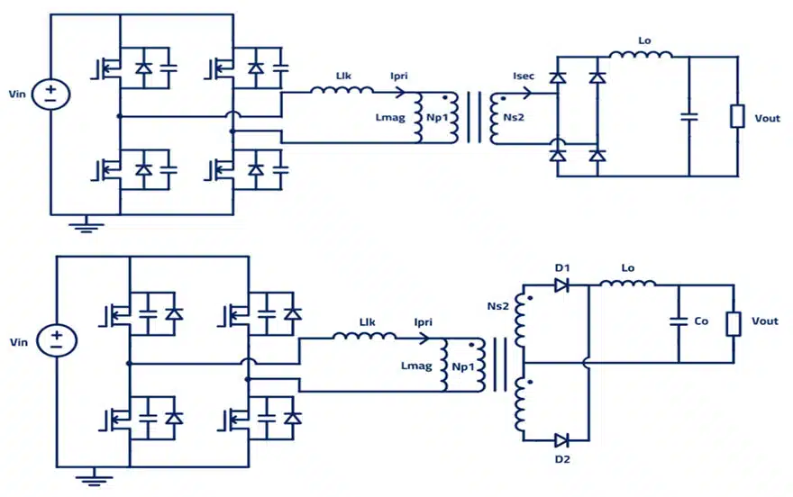
Phase-shifted full-bridge (PSFP) converter topology is normally used for high-power applications, with the representation of leakage inductance on the primary side. For this kind of design, we can have two different design objectives:

  1. Aim at the lowest leakage possible to reduce losses in the design
  2. Aim for a specific leakage inductance to achieve Zero Voltage Switching (ZVS)
Figure 1. Phase-shifted full-bridge PSFB converter topology circuit

LLC Half bridge and Full bridge

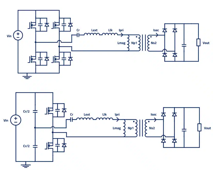
Figure 2. LLC resonant converter topology

As in PSFB, LLC resonant converter will have the same magnetics, but for the resonant tank: used in High power applications and with the leakage inductance representation on the primary side. The LLC topology will have:

Input inductor (with two design options):

  • Use it to achieve ZVS
  • Try to reduce its value by using the leakage inductance

Output filter

  • Controls sudden changes in the output
  • Controls the voltage in the output

In LLC we need to design the resonant tank, which includes the external inductor, leakage inductance and magnetizing inductance. All these inductors, with the resonant capacitor, will influence the resonant frequency of our converter. We need to choose them wisely to make our converter work. 

Dual Active Bridge DAB

With DAB as a bidirectional isolated DC/DC converter topology, we will be able to achieve bidirectional power transfer. Due to the topology design considerations, we will have an input inductor with the leakage inductance and the magnetizing inductance.

When we switch from one direction to the current inductor that we have on the primary side, will make the current change gradually.

Figure 3. Dual Active Bridge DAB topology

Forward Converter

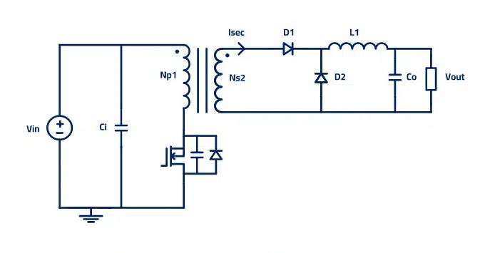
Figure 4. Forward converter topology

The forward converter is a DC/DC converter that uses a transformer to increase or decrease the output voltage (depending on the transformer ratio) and provide galvanic isolation for the load.

Used for low-power applications, it has an output filter to control the spikes and sudden changes at the output. Some further considerations for the forward converter:

  • The output inductor makes the design not suitable for high-voltage applications compared to the flyback, but a good fit when high output currents are required.

Flyback Converter

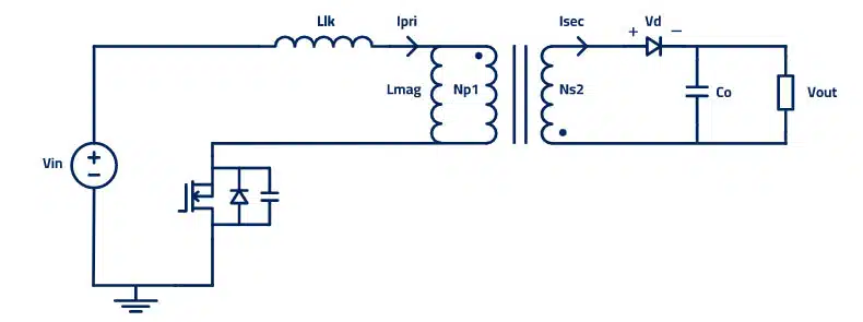
The flyback converter is a buck-boost converter with the inductor split to form a transformer, so that the voltage ratios are multiplied with an additional advantage of isolation. Flyback is used for low-power applications, and here the leakage inductance will be represented on the primary side. Further considerations:

  • It provides isolation from mains voltages
  • Since it doesn’t have an output inductor, as the forward topology does, we will have a high output ripple current. Therefore, Flybacks are more suitable for higher voltage applications instead of higher current.
Figure 5. Flyback converter topology

Summary

All the topologies for transformers and the flyback converters are composed of several magnetics that influence every part of the design. The key to a successful outcome is to design them correctly. 

Frenetic Online tool can have a several benefits, such as:

  • Fast iteration & design process
  • Easy access to results
  • Support provided by an engineering team expert in magnetics
  • Prototyping

By using Frenetic you can reduce the time to final designs, taking into account all the magnetic components that you can have in your designs.

Related

Source: Frenetic

Recent Posts

Microhardness — the Hidden Key to Understanding MnOx Cathode Quality in Tantalum Capacitors

3.11.2025
3

Lightweight Model for MLCC Appearance Defect Detection

3.11.2025
1

Bourns Releases High Current Metal Alloy-based, Multilayer Power Chip Inductors

31.10.2025
21

Common Mode Chokes Selection for RF Circuits in Next-Generation Communication Systems

30.10.2025
12

Capacitor Self-balancing in a Flying-Capacitor Buck Converter

30.10.2025
18

Vishay Releases Space-Grade 150 W 28V Planar Transformers

29.10.2025
20

How to Select Ferrite Bead for Filtering in Buck Boost Converter

23.10.2025
46

Power Inductors Future: Minimal Losses and Compact Designs

30.10.2025
57

Bourns Unveils Automotive 3 Watt Gate Driver Transformer

22.10.2025
10

Percolation Phenomenon: Degradation of Molded Power Inductors in DC/DC Converters

30.10.2025
59

Upcoming Events

Nov 4
10:00 - 11:00 PST

Design and Stability Analysis of GaN Power Amplifiers using Advanced Simulation Tools

Nov 4
November 4 @ 12:00 - November 6 @ 14:15 EST

Wirebond Materials, Processes, Reliability and Testing

Nov 6
14:30 - 16:00 CET

Self-healing polymer materials for the next generation of high-temperature power capacitors

View Calendar

Popular Posts

  • Buck Converter Design and Calculation

    0 shares
    Share 0 Tweet 0
  • Boost Converter Design and Calculation

    0 shares
    Share 0 Tweet 0
  • LLC Resonant Converter Design and Calculation

    0 shares
    Share 0 Tweet 0
  • Flyback Converter Design and Calculation

    0 shares
    Share 0 Tweet 0
  • Ripple Current and its Effects on the Performance of Capacitors

    3 shares
    Share 3 Tweet 0
  • MLCC and Ceramic Capacitors

    0 shares
    Share 0 Tweet 0
  • Dual Active Bridge (DAB) Topology

    0 shares
    Share 0 Tweet 0
  • SEPIC Converter Design and Calculation

    0 shares
    Share 0 Tweet 0
  • What is a Dielectric Constant and DF of Plastic Materials?

    4 shares
    Share 4 Tweet 0
  • Flying Capacitors

    0 shares
    Share 0 Tweet 0

Newsletter Subscription


Passive Components Blog

© EPCI - Leading Passive Components Educational and Information Site

  • Home
  • Privacy Policy
  • EPCI Membership & Advertisement
  • About

No Result
View All Result
  • Home
  • Knowledge Blog
  • PCNS

© EPCI - Leading Passive Components Educational and Information Site

This website uses cookies. By continuing to use this website you are giving consent to cookies being used. Visit our Privacy and Cookie Policy.
Go to mobile version