
The paper introduces development of NanoLamTM DC Link film capacitors, solid state, polymer monolithic capacitors, comprising 1000s of nano-thick, cross-linked polymer dielectric layers. The NanoLam amorphous polymer dielectrics have an intrinsic breakdown strength >1000V/mm, can withstand temperatures >200°C and have stable capacitance and dissipation factor with temperature and DC bias .
the paper was presented at the 2nd PCNS 10-13th September 2019, Bucharest, Romania as paper 1.1.
By A. Yializis Ph.D., PolyCharge America Inc., Tucson, Arizona
ABSTRACT
DC-link capacitors are used in power electronic switching circuits, including inverter modules for electric drive vehicles, to minimize ripple current and voltage transients. In voltage-sourced automotive inverters, the general requirements for the DC-link capacitors are benign failure, high ripple current capacity, low dissipation factor, high operating temperature and low cost. Metallized polypropylene (PP) film capacitors that service most DC-link applications today are rated at 95°C and can be used up to 105°C with significant derating in ripple current and operating life. PP DC-link capacitors are one of the largest, heaviest and most costly components in an inverter.
These limitations have been addressed with the development of NanoLamTM, solid state, polymer monolithic capacitors, comprising 1000s of nano-thick, cross-linked polymer dielectric layers. The NanoLam amorphous polymer dielectrics have an intrinsic breakdown strength >1000V/mm, can withstand temperatures >200°C and have stable capacitance and dissipation factor with temperature and DC bias. NanoLam capacitors represent a transformational and potentially disruptive change not only in their performance characteristics but also in the way in which polymer capacitors are produced.
The film extrusion plant, metallizer, and winding machine used to produce PP film capacitors are essentially replaced with a single apparatus fed with metal wire and liquid monomer, resulting in a multilayer capacitor material. This process places key capacitor properties such as polymer chemistry, dielectric constant, dielectric thickness and material cost, directly under the control of the capacitor manufacturer. In a single process step, a large area nanolaminate composite is formed, which is segmented and processed into individual capacitors. NanoLam capacitors developed for inverter applications are prismatic, have low ESR and ESL, an operating temperature range of -60°C to +125°C and excellent self-healing properties, resulting in capacitors that are at least two times smaller than metallized PP capacitors.
1.0 INTRODUCTION
Most electric motors in Electric Drive Vehicles (EDV’s) are driven with variable AC voltage, supplied by an inverter that converts the DC battery voltage to three-phase AC. A key component of the inverter circuit is the DC- link capacitor, used to minimize ripple, voltage fluctuation and transient suppression. The DC-link capacitor is one of the largest, and most failure-prone components in today’s electric drive inverter systems.
Although many advances have been made in power semiconductors, little has been done to develop efficient DC-link capacitors, which are a critical component of inverter circuits. Automotive OEMs that require high reliability components have moved away from electrolytics and use exclusively metallized polypropylene (PP) capacitors that have low loss and self-healing properties. These parts are typically rated at 400V-1000V and they are limited to an operating temperature of 105oC. This limited temperature range will not meet the full operating environment for automotive electronics without additional cooling for the capacitor, which limits packaging flexibility and increases system cost.
The PP polymer film dielectric has a relatively low dielectric constant (k=2.2), which translates into a large capacitor, occupying a large percentage of the EDV inverter volume. To compensate for the low k, capacitor manufacturers are extruding the PP material into thinner and thinner films. Although thinner dielectrics have higher breakdown strength, thinning of self-supported films such as PP, induces defects during the film production, slitting, metallizing and capacitor winding, which can effectively compromise the breakdown strength. In general, PP is fast approaching both its size and temperature limits, which makes it difficult to satisfy the requirements of new inverter designs that utilize SiC and GaN IGBTs and MOSFETs. Such power semiconductors operate at higher frequencies and require smaller DC-link capacitors that must handle higher ripple currents. The combination of lower capacitance and higher current, increases the thermal stress on the capacitor termination, which often leads to the use of larger PP capacitors than necessary by the inverter circuit, in order to minimize thermal load induced degradation.
Emerging capacitor designs include dielectrics utilizing ferroelectric and anti-ferroelectric dielectric media, using both conventional and nanostructured dielectric powders, glass dielectrics, new polymer film dielectrics and nanostructured polymer based dielectric materials [1-7]. If one imposes a benign failure mode, Multi-Layer Ceramic (MLC) and other technologies with poor self-healing properties are excluded. Polymer based nanostructured materials are still at an incipient technology level, mainly due to the poor nanoparticle uniformity in the polymer matrix and poor breakdown strength which offsets gains in dielectric constant. This leaves conventional high temperature films such as PPS, PEN, PI, PTFE/FEP and new polymer film dielectrics that combine high temperature and higher dielectric constants as a potential candidates for high temperature and energy density capacitors [8,9]. Major limitations to these new polymer films include the following:
- Increased dissipation factor at high temperature
- Thin films are difficult to produce, which compromises energy density at the lower voltages due to redundant dielectric strength
- Most high temperature polymer films, incorporate aromatic compounds that limit the self-healing properties
- Cost per joule is high and will remain high unless such films find high volume applications outside the capacitor market.
In summary, the alternatives for metallized PP are limited and this is why metallized PP that has limited temperature range and energy density is still in use today. Therefore, there is a clear need to develop high energy density, lightweight, high reliability DC-link capacitors that have low ESR and ESL, operating voltage in the range of 48V- 1000V+ and operating temperature in the range of -40°C to 125oC or higher.
PolyCharge America, (a Sigma Technologies Int’l spinoff in partnership with Delphi Automotive), has developed a new metallized polymer capacitor technology that addresses the PP dielectric limitations. Instead of producing a self-supported film, a large area solid state, polymer nano-laminate composite (NanoLamTM) is produced, comprising 1000s of high temperature, submicron polymer layers and aluminum electrodes. The large area composite is segmented and processed into individual multilayer capacitor elements that vary in area from a few millimeters to tens of centimeters.
The current supply chain to manufacture metallized film capacitors involves a film manufacturing operation, an electrode metallizing operation and a capacitor manufacturing operation. PolyCharge NanoLam Technology reduces the manufacturing process and supply chain to single operation where aluminum wire and a low cost radiation curable monomer liquid are introduced into a machine that converts them into a large nanolaminate composite [10-12]. This allows a capacitor OEM to innovate and produce components designed for specific applications by having control of the polymer chemistry, the dielectric thickness, and the electrode metallization. NanoLam capacitors have excellent self-healing properties with superior energy density. Unlike PP films that have a thickness limit of 2.2mm-2.5mm, NanoLam dielectrics have a thickness limit of 0.1mm and a wide range of dielectric constants (2.6<k<9.0), which can address high voltage as well as low voltage applications, allowing NanoLam capacitors to compete with polymer films, aluminum electrolytics and MLCs.
2.0 FORMATION OF THE NANOLAM MATERIAL
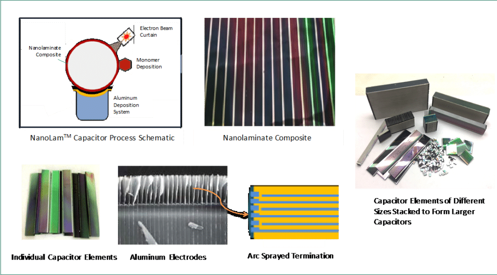
The NanoLam capacitor material is formed using a continuous high speed process, starting with a liquid monomer that is deposited on a process drum that is rotating at a speed of 200-500ft/min (see Figure 1). The liquid monomer layer is cross linked using an electron beam curtain. Heavy edge aluminum electrodes are deposited onto the polymer dielectric and the process is repeated for 1000s of layers. The mother capacitor material is then removed from the process drum and segmented into cards which are segmented into individual strips that are processed into capacitor elements. Depending on the capacitor size, a single batch of mother capacitor material can in result in 100s to 1000s of capacitor elements.
Key process steps in manufacturing NanoLam capacitors include the following:
- Nanolaminate Composite: The thickness of the composite material varies mainly with the dielectric thickness and the number capacitor layers, which is typically in the range of 1000 to 5000 layers.
- Segmentation into Cards: The nanolaminate composite is removed from the process drum and is segmented into smaller capacitor plates.
- Capacitor Element Formation: The capacitor cards are segmented into individual capacitor elements by removing the polymer on the two termination edges that exposes the aluminum heavy edge.
- Termination – Arc Spray: The 1000s of exposed aluminum layers are shorted together using a conventional arc spray process
- Assembly into Larger Capacitors: The individual capacitor elements which can vary in size from 1-2mm2 to 100cm2 or larger, are tested and can be used as single element capacitors or they can be stacked to form much larger capacitors.

3.0 THE POLYMER DIELECTRIC
The materials used to formulate the polymer dielectric are polyfunctional acrylate monomers, comprising mono, di, and tri-functional components designed to optimize the dielectric and self-healing properties of the capacitor. Major considerations which led to selecting the acrylate monomer chemistry to form high quality capacitor dielectric include:
- Rapid cure response ensures economical production speeds.
- A wide selection of polymer chemistries with broad range of chemical and physical properties.
- They form amorphous polymer pinhole free films that have excellent breakdown strength and high temperature properties.
- Commercial availability from a number of vendors ensures sufficient supply and low material cost.
4.0 NANOLAM CAPACITOR PERFORMANCE
4.1 Thermal Stability
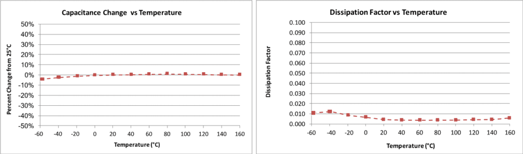
NanoLam capacitors are designed to operate in the temperature range of -40oC to 125oC. The maximum operating temperature is limited more by the capacitor package than the multilayer capacitor elements. Figure 2, shows a typical capacitance and dissipation factor stability characteristic as a function of temperature. Both capacitance and dissipation factor are stable with temperature up to the glass transition (Tg) of the dielectric which is greater than 180oC.
NanoLam capacitors are exposed to temperatures well above 200oC as part of the manufacturing process. Full size capacitors can withstand temperatures as high as 180oC for 10s of hours under rated operating voltages without a catastrophic failure. If operated at 180oC for extended periods of time the failure mode is one of capacitance loss. The capacitance loss is due to corrosion of the aluminum electrodes – not electrode loss due to a cumulative effect of self-healing events. Breakdown strength of the polymer dielectrics is not significantly reduced even at such high temperature.

4.2 Breakdown Strength
The intrinsic breakdown strength of the NanoLam dielectrics is greater than 1000V/mm, which is significantly higher than that of the PP film dielectric. The high breakdown strength is a result of mainly two factors: a) the dielectric thickness and b) optimization of self-healing properties.
a) Dielectric Thickness
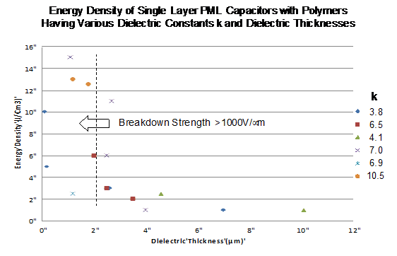
The effect of dielectric thickness on breakdown strength is an important and unique parameter for NanoLam capacitors. Specifically, we have found that as the thickness of the polymer dielectrics decreases the breakdown strength (or energy density) of the capacitors increases and can exceed 10J/cc. In the absence of crystalline regions in a polymer dielectric, a simplified avalanche dielectric breakdown theory dictates an inverse exponential dependence on dielectric thickness. The exponential dependence comes from the expectation that the change in current (dj) as a function of position between the electrodes (dx) will be proportional to the current j at that point:
dj / dx = kj or j ∝ ekx where k is a constant.
If the critical power density at which gaseous combustion products or vaporization products form is designated as Pc, then we find that the breakdown field, Eb depends on distance as:
Eb = Pc / j or Eb ∝ e-kx.
This simplified theory serves to substantiate the concept of increasing breakdown fields with decreasing layer thickness. Figure 3, shows experimental data of capacitor energy density as a function of layer thickness of NanoLam polymer dielectrics with different dielectric constants. This data is derived using single layer, double metallized capacitors with an area of approximately 300cm2. The data shows that regardless of dielectric constant the energy density or breakdown strength (V/mm) increases as the dielectric thickness decreases.
NanoLam capacitors with one thousand 0.5mm thick dielectric layers with a 5cm2 area and an electrode thickness optimized for high breakdown voltage, withstood 1000V, demonstrating an intrinsic breakdown strength of over 1000V/mm.

In order to utilize the high breakdown strength of sub-micron dielectrics, most NanoLam capacitors are produced using internal series sections as shown in the Figure 4.

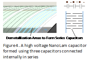
The demetallized zones are only 100s of microns thick which allows a large number of series sections to be used without significant loss in energy density. Small size NanoLam capacitors have been produced with multiple internal series sections, that can withstand voltages greater than 10,000V
b) Optimization of Self-healing Properties
Effect of Polymer dielectric : The chemistry of the polymer dielectric in addition to its effect on capacitance and dissipation factor, has a significant effect on the self-healing properties of the capacitor, which in turn affects breakdown voltage and leakage current. Specifically, the ability of a metallized capacitor to self-heal at a given electrode and dielectric thickness is to a large extent a function of the O:C and H:C ratios in the chemical structure of the polymer dielectric [13]. During a breakdown event the arc temperature causes the polymer to pyrolyze, which leads to a self-healing event by the removal of carbon and aluminum from the breakdown site in the form of Al2O3, CO, CO2, CH3, CH4, and other hydrocarbon gases. Metallized PP capacitors self-heal due to the high H:C ratio in the PP dielectric and the presence of an air gap between the wound (or stacked) metallized film layers. The importance of the air gap is often overlooked. As a result the majority of metallized capacitors that fail catastrophically fail toward the center of the roll where the interlayer pressure can be high enough to eliminate the air gap. The lack of an air gap along with other effects caused by the high interlayer pressure, when combined with high temperature, can lead to a non-self-healing breakdown event. So it is not unusual to unwind a catastrophically failed metallized PP capacitor roll that has 100s of clearings (self-healing events) in the outermost and innermost layers, with no clearings in the inner turns other than failure site. The function of the air gap in a NanoLam capacitor is replaced by oxygen in the molecular structure of the polymer dielectric to maximize the O:C and H:C ratios.
Effect of The Metal Electrodes: Early-on in the development of the metallized capacitor technology a capacitor development group at GE demonstrated that the energy dumped in a clearing site is, among other factors, proportional to the square of the electrode thickness and inversely proportional to the electrode resistance [14]. This and other factors led to the development of heavy edge and segmented metallized capacitor electrodes which maximize capacitor self-healing properties. Metallized electrodes in NanoLamcapacitors have two unique properties. First, a heavy electrode edge that has a conductivity that is many times higher than that used in metallized PP capacitors; and second, higher electrode resistivity active area of the capacitor to maximize self-healing. Unlike metallized film capacitors that utilize a Zinc heavy edge, NanoLam capacitors have an aluminum heavy edge which is more conductive. Furthermore, given the high temperature of the acrylate based polymer dielectric, a thick layer of aluminum can be deposited without concern for polymer softening and wrinkling, which would be the case for PP films. NanoLam capacitor electrodes are protected from exposure to air and they undergo two separate treatments to maximize corrosion resistance. One treatment involves the formation of a non-hydrated barrier Al2O3 oxide layer A second treatment reacts the aluminum surface with an organic corrosion inhibitor that minimizes access to moisture. In this manner, a higher electrode resistance is used to minimize the energy of the self-healing discharges compensated by the high conductivity of the heavy edge to maintain a low ESR.
4.3 Current Carrying Performance
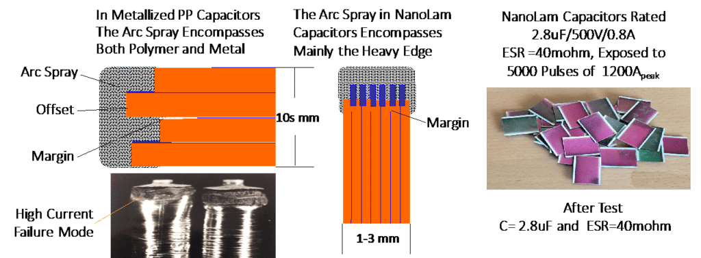
The termination of the NanoLam capacitors has several unique features that contribute to its ability to withstand high AC and di/dt currents. Figure 5, shows on the left a schematic of a conventional metallized film capacitor termination. The arc spray is imbedded between the extended polymer layers (offset) to make contact to the electrode heavy edge. In the NanoLam capacitor termination shown, the arc spray surrounds only the electrode heavy edge with virtually no penetration into the polymer surface. During thermal cycling the PP film, which has a high thermal expansion coefficient (TCE), expands and contracts significantly. When combined with high I2R heating, the PP dielectric at its temperature limit starts to lose mechanical strength, which results in gradual loss of contact with the arc spray as well as microcracking of the electrode layer. This increases the resistance (R) leading to a higher thermal load which if maintained will lead to catastrophic failure. In contrast, the arc spray in a NanoLam capacitor encompasses only the relatively thick heavy electrodes. The nanolaminate composite with a large number of aluminum layers per unit thickness, combined with a high temperature cross-linked polymer dielectric that loses little strength below 200C, has a TCE=40-50ppm/oC which is fractionally higher than that of arc sprayed Zinc. This, combined with a NanoLam capacitor element thickness of 1-2mm (vs 10s mm for a PP capacitor), results in a termination that is highly resistant to degradation induced by high AC and di/dt currents. An example of the high current carrying capacity of NanoLamcapacitors is shown in Figure 5, where small test capacitors that would ordinarily carry 0.8A are exposed to 5000 pulses of 1200Apeak at a high rep rate with no degradation to the capacitor termination.

5.0 NANOLAM CAPACITORS FOR MLC CAPACITOR REPLACEMENT
Multilayer Ceramic Capacitors (MLC) are in limited use in various inverters, including designs that require low profile parts that can handle high current and temperatures with no active cooling. MLCs are not self-healing and need to be tested at voltages of 2xVr. When combined with the requirement of high voltage and high capacitance, MLC parts are quite large, costly and are prone to micro-cracking. Factors that contribute to this failure mode include mechanical shock, thermal shock and, mechanical resonance due to their piezo-electric properties induced by the switching frequency of the power semiconductors. NanoLam capacitors were developed to replace MLC capacitors in an aerospace application where short failures were attributed to a mechanical resonance. Figure 6, shows a comparison of key dielectric properties of a NanoLam capacitor designed for replacement of the MLC capacitor.

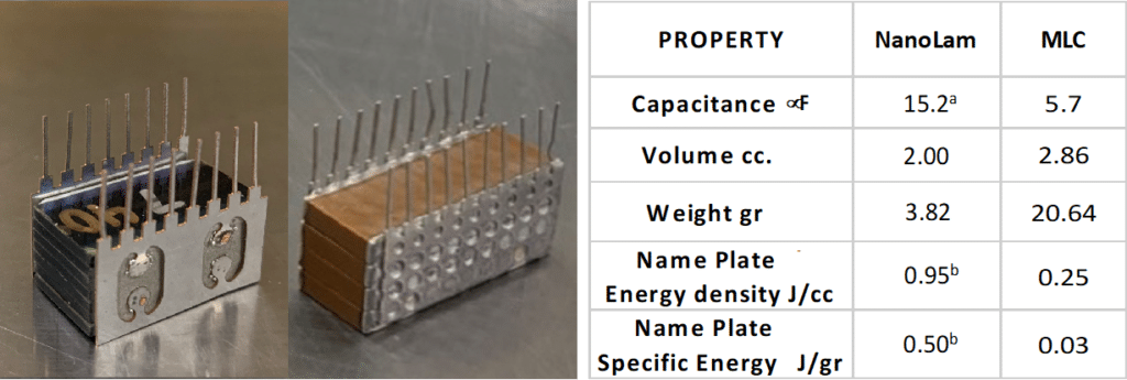
- The PML capacitance is constant with DC bias and temperature while the MLC will experience a significant drop in capacitance with bias and temp>100C.
- The actual energy density and specific energy of the PML cap will be even higher when the MLC capacitance change with bias and temperature is included in the calculation
In addition to their higher energy density and specific energy, NanoLam capacitors will add a higher level of reliability due to their self-healing properties, at a fraction of the MLC cost.
6.0 FACTORS CONTRIBUTING TO THE HIGH ENERGY DENSITY OF NANOLAM CAPACITORS
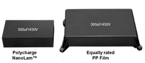
When compared to metallized PP capacitors the high energy density of NanoLam capacitors (see comparison with PP capacitors in Figure 7) is due to several factors which include the following:
- Superior breakdown strength of submicron dielectrics
- Higher dielectric constant (k=3.2 or higher, versus k=2.2 for PP film)
- Capacitor margins are significantly smaller than that of metallized film capacitors

The sub-micron dielectric which was addressed above and the smaller margins are unique to the NanoLam technology. The effect of the smaller margins is schematically shown in Figure 5. Metallized capacitors have an offset between the two wound films to facilitate bonding of the arc spray termination and a non-metallized margin to prevent flash-over to the opposite electrode. The length of the non-metallized margin is a function of the maximum applied voltage and it is significant for voltages >500V. A NanoLam capacitor has no offset and the margins are a small fraction of those in film capacitors.
The reason for this is because in a NanoLam capacitor, the next deposited polymer layer fills the margin with polymer dielectric which has much higher breakdown strength than a flash-over on the PP film surface. This unique feature of NanoLam capacitors does not only reduce the capacitor size, but it allows to produce capacitors that have a small termination to termination distance, which also minimizes ESR and ESL and improves heat dissipation.
This is highly desirable for many inverter designs, because it has a significant impact on the inverter volume and shape. An example of this is the NanoLam capacitor shown in Figure 6, which comprises internal series sections with a total termination to termination width of 10mm.
Larger capacitors (e.g. 500mF – 1000mF) can be made using the same nanolaminate material by cutting the capacitor elements longer and stacking more of them in parallel. Such flat shape is not efficient for a PP capacitor because the length of the two film off-sets and the two margins will consume most of the 10mm space, leaving little room for the active capacitor area.
7.0 CONCLUSIONS
NanoLam capacitors, designed specifically for DC-link applications, have several differentiating features when compared to metallized PP film capacitors. They have a high temperature polymer dielectric with optimized O:C and H:C ratios to maximize self-healing performance. They have higher energy density, derived mainly from the use of sub-micron polymer dielectrics which, in combination with a prismatic shape, results in a lower ESL. They can handle higher ripple and di/dt currents. The somewhat lengthy supply chain of PP film capacitors is replaced with a single step process that is performed by the capacitor OEM. This allows a capacitor OEM to control key capacitor manufacturing parameters such as dielectric thickness, dielectric constant, glass transition temperature, self-healing properties and electrode metallization. PP capacitor manufacturers have difficulty innovating when most source the same base PP dielectric from a handful of film suppliers worldwide. In contrast NanoLam dielectrics can be customized for different applications. Finally, when compared to high voltage and high capacitance MLCs, NanoLam capacitors have higher energy density, dramatically higher specific energy and are not prone to micro-cracking and shorting.
8.0 BIBLIOGRAPHY
- Y. Jun Zeng, Renli Fu, Shen, S. Zhang, Q.M. Zhang, Polymer Based Dielectrics With High Energy Storage Annual Rev. Mater. Res. 2015. 45:433–58 – Review Paper
- H. R. Jo and C.S. Lynch, A high energy density relaxor antiferroelectric pulsed capacitor dielectric Journal of Applied Physics 119, 024104 (2016)
- Q. Li, K. Han, M.R. Gadinski, G. Zhang, and Q. Wang, High Energy and Power Density Capacitors from Solution‐Processed Ternary Ferroelectric Polymer Nanocomposites, Advance Material V. 26, Issue 36, 2014
- Z.M. Dang, J.K. Yuan, S.H. Yao and R.J. Liao,. Flexible nanodielectric materials with high permittivity for power energy storage. Adv. Mater. 25(44):6335–65, 2013
- L. S. Zhai J. Wang, J. Xue, S. Zhang. Enhanced energy storage density in poly(vinylidene fluoride) nanocomposites by a small loading of surface-hydroxylated Ba0.6Sr0.4TiO3 nanofibers. ACS Appl. Mater. Interfaces 6(3):1533–40, 2014.
- Te-Chuan Chen, L. Wang, G. Goodyear, A. Yializis, and H. Xin, “Broadband Microwave Characterization of Nanostructured Thin Film With Giant Dielectric Response”, IEEE Transactions On Microwave Theory And Techniques, Vol. 63, No. November 2015
- M. Lanagan, “Glass Dielectrics for DC Bus Capacitors”, DOE Vehicle Technologies Program APEEM R&D FY13 Meeting, Oak Ridge, TN, Nov. 13-15, 2012
- N. Venkat, T.D. Dang, Z. Bai, V.K.McNier, J.N. DeCerbo, B. Tsao and J. Stricker High temperature polymer film dielectrics for aerospace power conditioning capacitor, Materials Science and Engineering B, V. 168, Issue 1-3, 2010
- D. Tan, L. Zhang, Q. Chen and P. Irwin, High-Temperature Capacitor Polymer Films, J. Electronic Materials, V. 43, Issue 12, pp4569-75, 2014
- A. Yializis and Yuji Ozaki, “ Solid State Polymer Multilayer (PML) Capacitors” Electronic Components Industry Association (ECIA) (also known as CARTS), Huston TX, March 2013
- A. Yializis, G. Goodyear, “Advance High Energy density Capacitors”, Advance Capacitors World Summit, March 31, 2009, Lajolla,Ca.
- A. Yializis and T.A. Miller, “Electrostatic Supercapacitors”, Fifth International Seminar on Double Layer Capacitors and Similar Energy Storage Devices, Dec. 4-6, Boca Raton, FL,(1995).
- A Yializis “Metallized Capacitor Chapter” in the Handbook on Solid state Batteries and Capacitors by M. Zafar A. Munshi -1995 – Science – 716 pages
- D.G. Shaw, S.W. Cichanowski, G.R. Newcombe and A. Yializis “Electrical Properties and Aging Mechanisms in Metallized Film Capacitors”, 1982 IEEE International Conference on Electrical Insulation, June 1982

