
EMC noise is a common issue related to use of electrical drives. The following article published by Electronics Weekly written by Christofer Kronschnabl and Wolfgang Ernst of Panasonic discuss use of capacitors and inductors to suppress these effects.
State of the art AC motor control applies power switch transistor arrays, steered by a microcontroller for all dynamic parameters. Their fast switching of the commutation and overlaid Pulse Width Modulation (PWM) scheme provide lowest power loss due to short transients and low on resistances.
As a result compact, more efficient and motor integrated electronics are moving towards higher power ranges.
Motor DC power supply
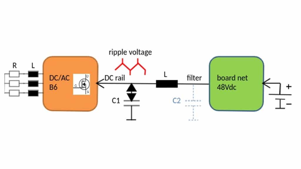
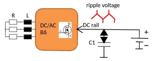
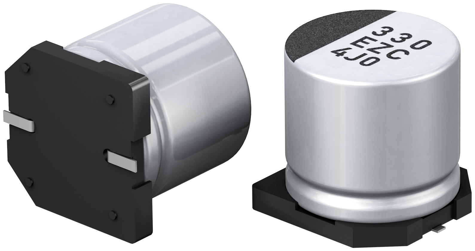
A power switch for e. g. a B6 brushless 3-phase motor is supplied by a DC voltage of e. g. 48V from a car battery via a board net line. The ripple current drawn from the semiconductor array should not rush into the power source, therefore a capacitor bank C is needed to bypass it. These capacitors, e.g. hybrid polymer capacitors, carry all demanded ripple currents at a low total ESR thus keeping the ripple voltage low.
EMC problem

A good semiconductor bridge and motor design contributes to low radiation itself, supported by the inductive nature of a motor impedance and short connections. However at the drives DC input line a ripple voltage up to hundreds of mV is present, with peaks at the maximum motor currents e. g. during startup loaded by a high inertia.
The connected DC power line is designed for a low impedance and acts as antenna which radiates the ripple voltage power at certain frequencies. The ripple voltage waveform shape is mostly a sawtooth/square at a PWM fundamental frequency of several tenths of kHz. The resulting harmonics provide substantial power even at several hundreds of kHz, located well above the 150kHz lower boundary of the CISPR25(2016) requirements for vehicles.
Countermeasures for avoiding radiation from the DC supply line
A common countermeasure to radiating switch noise is to provide AC impedance on a power supply cable by clamp ferrites (not shown). Saturation even under the highest DC load current at tenths of amps may not occur because impedance should not go down, therefore a certain size is required.

But place in a vehicle is rather limited, and furthermore the ferrite performance depends on the location where it is applied and some more application dependent boundary conditions.
A better solution is to omit all ferrite clamps and providing an inductor L near the ripple voltage source, as shown below.
Onboard countermeasure against ripple radiation from the from the DC supply line
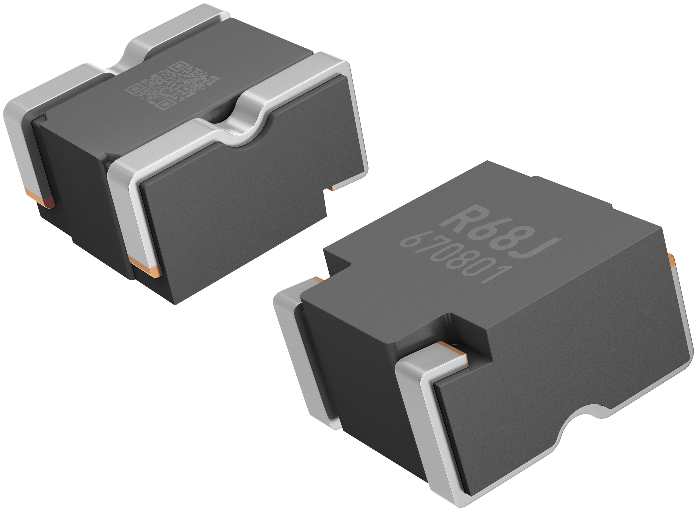
A ripple voltage can never be avoided, but decoupled very effectively from the DC power input parts with a surface mount inductor. Compact inductors (such as Panasonic ETQP series) can handle high DC currents at very low saturation effects due to the fully molded iron powder body. Moreover, the precise windings provide the inductance up to very high frequencies, making them ideal for a filter application.
Optionally an additional small capacitor at the 2nd inductor terminal (dashed blue colour on image above) would suppress the noise in the upper frequency range even more.
Advances of the onboard inductor proposal
Reducing the cost and lines for an automotive board net are the clear targets for new vehicle designs.
As the complexity of electrification in a car increases the EMC requirements increase even more. Drives should fulfill EMC requirements by design, not by additional parts to place around. The power choke coil (Panasonic ETQP) is very effective to provide EMC for a compact electric drive.
Additionally the design of the drive becomes more universal, the risk to fail EMC requirements under individual external circumstances is strongly reduced.
Which inductor is recommended?
The largest radiation peak is likely to occur at the largest current fed to the motor. Unfortunately just at this peak the DC current passing through a filter is largest and reduces inductance by saturation effects. As a result the inductance drops, the low pass filter roll off slope shifts to higher frequencies and increases the harmonics feedthrough. Therefore rather low saturation up to the highest DC inrush current is mandatory. Moreover additional physical effects of the real inductors contribute to increase bypass especially at the higher frequency signals under current load.
Conclusion
Even if power choke inductors of similar size and technology can perform in a similar manner under low load, the ability to filter under DC load is quite different. It is important to consider the more advanced inductors (Panasonic ETQ-P) which are much more stable under load and minimize the bypass of radio frequencies by design.
This performance was achieved by the applied Panasonic proprietary magnetic material combined with an optimized windings and terminations design, targeting to fulfil as well the harsh requirements in high temperature automotive environments. A long in house experience led to superior performance especially where low thermal management efforts in small spaces along with best ac performance e. g. for a power conversion stage with a high output dynamic range but keeping highest efficiency are requested.
the article was modified in its original content

