
Engineers designing power electronics find that capacitors are needed for several functions, from energy storage to filters and decoupling. Different capacitor types are available, that at first sight might seem equivalent in their headline ratings of capacitance and voltage, but would not perform equally. Incorrect selection can lead to, at best, an expensive ‘over-engineered’ solution and, at worst, an unreliable or unsafe product.
This paper describes the different types of capacitors that might be considered for use in power electronics applications. Particularly, electrolytic and film capacitor types are compared showing how and when each has a role. The variety of film types and their construction are described in more detail and preferred types identified. Specifications for capacitance, ripple current rating, transient voltage immunity and safety rating, along with other characteristics are examined in detail.
The phenomenon of ‘self-healing’ after voltage stress is discussed explaining its physical mechanism and the value it confers in typical circuits. The main applications for film capacitors in power electronics are identified and guidance given on how to select appropriate film capacitor types. Detailed calculations are then given for some example circuits showing how particular capacitors and their ratings are selected. Calculations are generalized to enable engineers to use them as a basis for their designs.
It is hard to imagine any modern electronics that do not include capacitors of some type. They may be vanishingly small surface-mount types in cell phones for example, but they are still there. In power electronics, the function is filtering, energy processing, and transfer, and in contrast, capacitor volumes can be measured in cubic inches. In this application, there is sometimes a seeming choice between aluminum (Al) electrolytic and film types but in terms of stored energy density, Al-electrolytics are in some ways ahead.
The only comparable film types are exotic and expensive such as ‘segmented high-crystalline metallized propylene’ which even then, do not maintain their ripple current rating well at high temperatures. Al-electrolytics have a relatively poor reputation for life and reliability, but this only applies if they are worked hard. Suitably derated with voltage, ripple current, and temperature, they can last many years. Their low cost for a given capacity-voltage (CV) rating is, of course, a significant factor. This means that they are the practical solution for high-volume energy storage applications such as on the internal high-voltage DC bus of commodity AC-DC power supplies.
Film Capacitors Have Their Place in Power Electronics
Film capacitor types certainly do have some advantages over their Al-electrolytic cousins; they can have much lower Equivalent Series Resistance (ESR) for the same CV rating, which gives them typically much better ripple current ratings. They are also relatively more tolerant of voltage over-stress and significantly, can in some cases ‘self-heal’ after a degree of breakdown, enhancing system reliability and lifetime.
When localised breakdown does happen, a short circuit forms in the body of a film capacitor but a plasma arc occurs which acts to clear the short. This works only within stress limits though; catastrophic failure can still occur due to carbon deposition and collateral damage to the dielectric insulation. In practice, Al-electrolytics can only withstand typically 20% voltage overstress while the figure for film types can be 100% for a limited time. The difference in failure mode is significant as well; Al-electrolytics will often go short after overstress with explosive results causing discharge of liquid electrolyte and damage to other components.
It is true that theoretical failure rates for Al-electrolytic and film types can be comparable with correct derating, but in real-life applications with occasional voltage stress from, for example, inductive loads or lightning strikes, system reliability can be entirely different between the two technologies. Degradation due to humidity is an issue for film capacitors but this is in common with other components so should be controlled for best reliability.
When energy storage is not the headline parameter, large value film capacitors can be a high-performance solution. An example would be on a battery-backed DC bus such as you see in electric vehicles, alternative energy systems, and uninterruptible power supplies. In these applications, the primary function of the capacitor is to source and sink high-frequency ripple current that could be measured in hundreds or thousands of amps where low capacitor ESR is vital to achieving low losses and low ripple voltage.
The move to higher bus voltages also favors film capacitor types; the same energy is stored with smaller CV ratings at high voltage (due to the ‘squared’ in E=CV2/2) so less capacity is needed, and film types are available with kV ratings as required. Al-electrolytics are limited by their technology to about 550V and although they can be stacked for higher voltage, they have inherent high and variable leakage current requiring parallel balancing resistors with their associated cost and losses. We discussed the short-circuit failure mode of Al-electrolytics; when in series, one failing this way will then place high voltage across the others, with an avalanche of consequential damage.
A practical difference between film and Al-electrolytic capacitors is their mounting options. Film is available in volumetrically-efficient rectangular box formats with a choice of wire, screw, lug, push-on connector or even bus-bar terminations. For Al-electrolytics, a round metal can is the only standard option although with a similar range of terminations available. Unlike Al-electrolytics, film types are non-polar, they can operate happily with either polarity of voltage applied making them reverse-proof. This also means that they are ideal for applications where AC voltage is applied such as in inverter output filtering.
We have talked about ‘film’ capacitors in general but there are many sub-types with differing performance and applications. Figure 1 [1] gives a summary of some types that might be used in power electronics with their main characteristics.

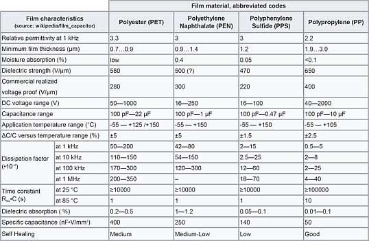
Amongst the performance data, polypropylene is a good contender for power applications, with its wide voltage and capacitance ranges and good self-healing performance. The particularly low figure for dissipation factor (DF) at all frequencies is important as well; DF is the ratio of ESR to capacitive reactance ZC = 1/2πfC.
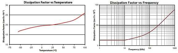
A low figure implies lower heating effects compared with other dielectrics and is a way of comparing losses per microfarad of capacity across capacitor types. Generally, DF varies a little with temperature and frequency, but polypropylene performs best in the comparison, see Figure 2 for plots.

For less critical applications in power, polyester can be an excellent low-cost choice with its high specific capacitance (CV per volume) and wide temperature range.
Polypropylene Capacitor Construction
Looking at polypropylene capacitors now in more detail, there are two basic constructions—metal foil and metal deposition, shown in Figure 3, taken from reference [2].

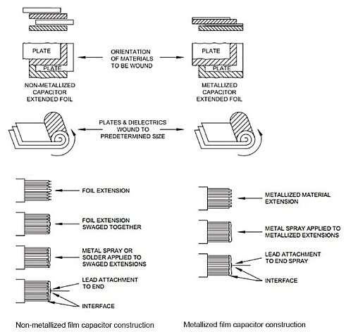
In the former, metal foil of about 5-micron thickness is sandwiched between dielectric layers and gives high peak current capability but no self-healing. In the metallized film construction, aluminum or sometimes zinc or zinc alloy at about 1200°C is deposited onto the polypropylene film under vacuum, to about 20 to 50nm thickness.
The film is held to a low temperature during the deposition, typically -25°C to -35°C. In this process, self-healing is enabled. In use, localized breakdown causes intense heating, perhaps up to 6000°C, which causes a plasma arc to form. This vaporizes the metallization locally and the rapid expansion of the plasma quenches the arc, isolating the defective area within around 10µs and allowing the capacitor to continue to function. Some capacity is lost but the effect is minimal, and it can be used as a measure of the aging of the component if monitored over time.
The metallization is sometimes segmented into areas on the film, perhaps millions, with narrow ‘gates’ feeding current into the segments and acting as fuses for gross overloads. The peak current handling is reduced a little by the narrowing of the total current path, but the extra safety margin introduced consequently allows the capacitor to be rated at a higher voltage.
In some designs, foil and metallization construction is combined to give compromise performance between peak current handling and self-healing. The metallization can also be graded from the edge of the capacitor so that thicker material at the edges gives better current handling and more robust termination by soldering or welding. The grading can be stepped or continuous.
Partial Discharge Effects
The polypropylene film used has a dielectric strength of about 650V/µm with thicknesses from about 2µm, so it is easy to get device voltage ratings of several kV with parts available at 100kV. There is an effect though that comes into play with very high voltages – partial discharge or ‘PD’. Sometimes called ‘corona,’ this is the breakdown of micro-voids in the bulk of the dielectric material or air gaps between insulating layers.
The effect is to insert a ‘partial’ short circuit into the insulation, effectively shortening the insulating path and locally reducing the breakdown threshold voltage. Each short puts extra stress on the remaining insulation, and as they accumulate over time, a tipping point is reached, and total breakdown occurs.
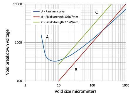
Detection of partial discharge relies on specialized equipment to register individual breakdown events by the transient extra current that flows during a high voltage test. The energy in the events is measured in pico-coulombs though and is difficult to detect, but is a good measure of the condition of insulation over time. The ‘Paschen curve describes the PD effect’, Figure 4, plot A, with its characteristic and little- understood ‘minimum’ in the relationship between micro-void size and breakdown voltage. Plots B and C are two example field strengths through an insulator—points above the Paschen curve (A) are likely to produce PD breakdown. PD has an ‘inception’ voltage for breakdown to start but a smaller ‘extinction’ voltage before breakdown stops.

Impregnating high voltage capacitors with oil helps with PD by displacing air, with its lower breakdown threshold, from insulation interfaces. Resin-filling lower voltage capacitors also help in this respect and additionally improves mechanical robustness.
PD is an effect cause by electric field intensity, kV/mm, so thicker dielectric material is less susceptible but at the expense of larger size components for the same CV rating. Capacitors can be connected in series so that individually they see lower voltage stress, below the PD inception point, but may need balancing resistors. Sometimes high voltage capacitors are formed from series elements in one housing to avoid PD.
Applications for Capacitors In Power Electronics
We mentioned that a critical application is capacitors on the DC bus of power converters or inverters and that the need for providing ‘ride-through’ or ‘hold-up’ was a differentiating factor in choosing Al-electrolytics or film capacitor types. It is perhaps illuminating to take an example and see how each type fits. Taking a 90% efficient, 1kW off-line AC-DC converter with a power factor corrected front end. Its internal DC bus operates at 400VDC nominal, falling to 300VDC before the converter stops regulating, Figure 5.

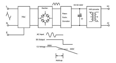
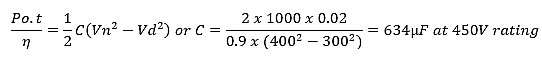
If 20ms ride-through is needed after a power outage, a capacitor is needed on the DC bus to provide the energy for the converter to continue operating with 1kW output for the duration of the outage. To calculate the capacitance required (C), we equate the difference in energy in the capacitor as it drops from 400V (Vn) to 300V (Vd), with the energy supplied to the converter, that is, power (Po) multiplied by time (t) divided by efficiency (η).

Choosing a conventional high-grade capacitor from the TDK line in their B43508 series, it would be about three cubic inches or 52cm3. To get the same overall capacitance and voltage rating from similar grade film capacitors in the TDK B32678 series, you would need 16 in parallel with a total volume of 98 cubic inches or 1600cm3. The difference is size is a factor of around 30 with a cost ratio of similar proportions.
In the case where ride-through is not a requirement but the capacitor is used to minimize ripple voltage on a 400VDC bus such as you might find in an EV application, typical values might be say, 80A rms of ripple current (Irms) taken by a downstream 20kHz converter with a maximum ripple voltage of 4V rms. Capacitance C can be approximated by:

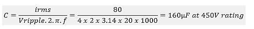
You sometimes see a rule of thumb for capacitors in this position of 20mA rating per µF, tying in with our result. There is a small, low-cost part in the TDK B43508 series rated at 180µF, 450V but with only a 3.5A rms ripple current rating at 60°C, including its frequency correction factor. We would, therefore, need 23 in parallel for 80A ripple, with an unnecessary 4140µF total capacitance and a volume of about 38 cubic inches or 621cm3, allowing for the poor packing factor.
The ESR of each capacitor is about 1ohm so with 3.5A rms, each will be dissipating about 10W. If we look at film capacitors, again from the TDK B32678 series, just four in parallel totaling 160µF, 450V give 132A rms capability with a volume of 24.5 cubic inches or 402cm3. The capacitor ESR is 2.5 milliohms, giving just 1W dissipation in each. The tables are turned, and the film capacitors are the correct choice with much lower dissipation, better over-voltage withstand an optimum capacitance and with far less inrush energy than would be the case with 4140µF. The film capacitors are easy-to-terminate wire-leaded box style and just four are needed.
A deciding factor on choice of capacitor may be cost rather than physical volume and dissipation so we can take the same two TDK series of capacitors, and compare value per joule of energy storage and per amp of ripple current rating. Using data from a high-service distributor [4], for around 180uF 450V rating, the Al-electrolytic type calculates to about $0.47/joule and the film type $3/joule for energy storage. For ripple current, the Al-electrolytic is $2.68/amp and the film type $0.42/amp. This shows how the nearly 6:1 cost advantage reverses, depending on the application requirement. In high volume, the absolute costs will be lower, but the ratios may remain similar.
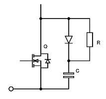
Film Capacitors as Snubbers
Another high-value application for capacitors in power converters is in ‘snubbing’ as snubber capacitor, the deliberate slowing of switching waveforms to reduce EMI and semiconductor stress (Figure 6). Here, the important consideration is the ability of the capacitor to withstand the high dV/dt or rate of change of voltage imposed which can push high rms currents into the component. Again, polypropylene is a good choice particularly when the metallization is double sided and when fabricated in combination with metal foil to take the high currents. Capacitors intended for the application will normally also have very low inductance terminations for low impedance to AC, and high voltage withstand margin to cope with the sometimes-indeterminate peak voltages encountered.

Film Capacitors as Power Filters
Although filtering is often seen as a signal level function, in inverters and motor drives particularly, output capacitors pass high ripple currents to prevent high dV/dt levels on cabling causing stress and EMI, see Figure 7. As AC is passed to the load, the capacitors must be non-polarised, anyway excluding use of Al-electrolytics. The application environment is often severe and the robustness, ripple rating and volumetric efficiency of polypropylene capacitors are necessary.

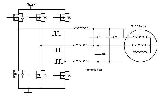
Figure 7 Film capacitors in motor drive EMI filtering.
EMI Filters
Film capacitors are used extensively in power line EMI filters, not so much for their ripple current ratings but for their self-healing property with the voltage transients that occur (Figure 8). Agency safety-rated polypropylene capacitors are typically rated as ‘X1’ or ‘X2’ when across the line withstanding 4kV and 2.5kV respectively and can be several µF in value to meet EMI standards. Capacitors from line to ground to attenuate common mode emissions are ‘Y1’ and ‘Y2’ types rated at 8kV and 5kV but are limited in value by line leakage current considerations. In these EMI filtering applications, the low self-inductance of typical film capacitors is an advantage, keeping self-resonances high.

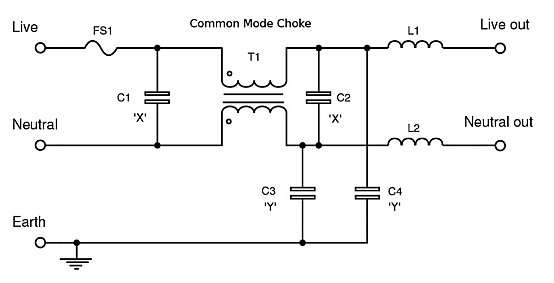
Figure 8 A typical power line filter with film ‘X ‘and ‘Y’ capacitors.
Conclusions
Film capacitors in power electronics find a wealth of applications and excel when high ripple current ratings are required or when the environment imposes over-voltage stress, polypropylene types being particularly valuable. When CV ratings of film and aluminum electrolytics are compared, a deeper analysis shows that although Al-electrolytic types win for simple energy storage considerations, practical component selection has to include ripple current rating and reliability considerations when film will often be a better choice.
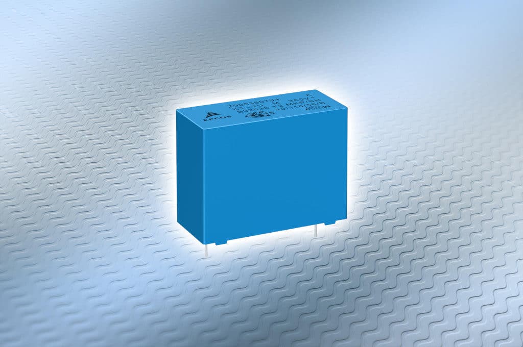
featured image source: TDK

