Impact of MLCC DC BIAS has been discussed in-depth in recent articles High CV MLCC DC BIAS and AGEING Capacitance Loss Explained, but how to simulate MLCC DC BIAS Capacitance Drop with LTSpice software? Reiner Bidenbach, Analog Devices field applications engineer propose a solution in his article published by Evertiq.
Q: How can I take the DC bias effect of multi-layer ceramic capacitors (MLCCs) into account in circuit simulations?
A: LTspice’s nonlinear capacitor capabilities and a reasonable model.
This article describes how LTspice simulations can be used to account for the effect of voltage dependence, or DC bias, caused by the use of ceramic capacitors with even smaller and smaller case sizes. Demand for smaller electronic devices with an increasing number of features, combined with reduced current consumption, calls for size constraints on components, including MLCCs. As a result, the effect of the voltage dependence, or DC bias, is also being pushed into focus.
Miniaturization of ceramic capacitors requires higher capacitance values in an increasingly smaller space. To that end, materials with high permittivities (ε) and increasingly thin dielectric insulating layers are being implemented, making it now possible to produce high quality ceramic layers on an industrial scale.
Unfortunately, the permittivity εr = ƒ(→E ) is a function of the electric field strength, and thus the capacitance exhibits a voltage dependence. Depending on the ceramic type and the layer thickness, this effect can be very pronounced. A drop in capacitance to less than 10% of the nominal value at the maximum allowable voltage is no rarity.
In applications that work with a constant voltage applied to the MLCC (for example, decoupling capacitors), the effect can easily be taken into account. As long as the voltage remains constant, the remaining capacitance value can be taken from the data sheet or an online tool provided by the manufacturer.
But what about cases in which the voltage is variable—for example, in Figure 4., which shows an input filter on a switching regulator that should be operated with 5 V from USB to 24 V from an industrial supply? Or the AC coupling of a 2-wire Ethernet PHY with supply on the same lines with different voltage values?
In such situations, circuit simulations with LTspice provide useful insight. Some MLCC manufacturers already offer the corresponding DC bias models for down- load. In addition, LTspice provides methods for imitating the voltage-dependent behavior with implemented tools. For this, the curve of capacitance as a function of voltage and one of the approaches described in Figure 3. are useful.
LTspice offers a well-known capacitor model with a constant capacitance as well as a nonlinear model. This nonlinear model evaluates a charge equation. Direct evaluation of a nonlinear capacitance model is unsuitable due to the required charge retention. This should not be a problem here because the capacitance is yielded through differentiation of the charge with respect to the voltage. Conversely, the integral of the voltage-dependent capacitance must be formed. This has already been done for the following approaches, so these models can be used without any math.
The first-order approach uses the linear voltage dependence
from which, through integration, the charge equation is yielded:
This can now be inserted directly in LTspice nomenclature in place of the capacitance value in the capacitor: Q=x*{c0V}-0.5*x**2*({c0V}-{cVmax})/{Vmax}.
In many MLCCs, however, the initially nearly constant capacitance drops rapidly even at moderate voltages, after which it remains nearly constant. If only the linear model is used in such cases, the effective capacitance is overestimated for a large range of voltages. For this widespread case, a model based on the hyperbolic tangent (tanh) can be used:
The parameters can be easily estimated without use of further aids – see Figures 1. and 2.
The capacitance value can also simply be replaced by the charge equation:
Q=x*({C0+Csat})/2+({Csat-C0})/4*{Vtra}*ln(cosh((x-{Vth})*2/{Vtra})).
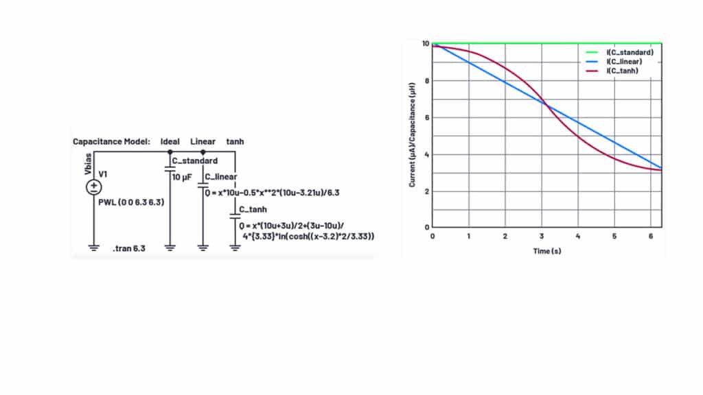
For checking the capacitor model in LTspice, a constant voltage ramp with
Figure 3 clearly shows the superiority of the proposed nonlinear models over the standard constant-capacitance model. With such a capacitance curve, the linear model is sufficient for most applications.
Finally, it should be noted that only a single nonideal effect is simulated here. There are still a number of other effects in MLCCs including aging, temperature dependence, frequency dependence, AC amplitude dependence, dielectric absorption, and many more. For many applications, it is sufficient to consider the DC bias dependence as the only dominant effect. LTspice can be used as a practical tool to account for nonidealities such as DC bias prior to manufacturing the first prototype.
