
Electronic component miniaturization and operation in harsh environmental conditions are growing trends in applications, such as on-board chargers, energy meters, capacitive power supplies, including connection in series with the mains, motor drives, wind and solar inverters. Current EMI (Electromagnetic Interference) X2 class suppression and DC-link power box film capacitors need capability improvement to meet these requirements.

Very high capacitance and dissipation factor stability are required during operational life in severe ambient conditions such as high temperature and relative humidity, while still meeting European and other Electrical Norms (ENEC and CQC), the criteria in the standard for automotive application (AEC-Q200) and the international safety requirement (UL). The moisture absorbed into the capacitor leads to corrosion of the electrode and accelerated degradation of the capacitor by increasing of capacitance loss. Temperature-Humidity-Bias (THB) is a standard test for accelerated stress testing of corrosion and other moisture-driven mechanisms for degradation. In this paper, we have studied the characteristics and performance under high temperature and humidity conditions of new capacitor designs in a miniaturized version of first to the market metallized EMI X2 class suppression and DC-link power box film capacitors. Three advanced KEMET series of metallized film capacitors have been stressed under an applied rated AC or DC voltage at 85°C and 85 %R.H. and the drop of capacitance and change of the dissipation factor have been monitored with the time for 500 and 1000 hours, respectively.
The paper was presented by Hristina Kostadinova Boshkova, KEMET Electronics Macedonia, North Macedonia at the 3rd PCNS 7-10th September 2021, Milano, Italy as paper No.5.1.
EMI SUPPRESSION AND DC-LINK METALLIZED FILM CAPACITORS
INTRODUCTION
Progress in semiconductor technologies, such as the implementation of MOSFET Wide Band Gap (WBG) devices and the implementation of diode devices, emphasizes the size miniaturization and increased performance of electronic components. However, reliability remains a concern when components and devices downsize and become more compact. The utilization of WBG semiconductor components in power conversion systems allows for smaller footprints and greater efficiency with lower energy losses during the energy conversion. Other key advantages include reducing audible noise and the miniaturization of passive components, all with the benefit of printed circuit board (PCB) real estate reduction. However, due to the ever-increasing number of electronic components integrated into smaller geometries, miniaturized devices have become increasingly susceptible to electrical noise or interference. While the use of higher frequencies in WBG devices helps to minimize audible noise, it produces more high-frequency emissions and requires more complex designs to meet emission requirements by regulatory agencies. For these reasons, EMI suppression capacitors play a crucial role in the electronics industry, with the need for more miniaturized solutions under critical electrical and environmental applications.
Metallized film capacitors in EMI suppression
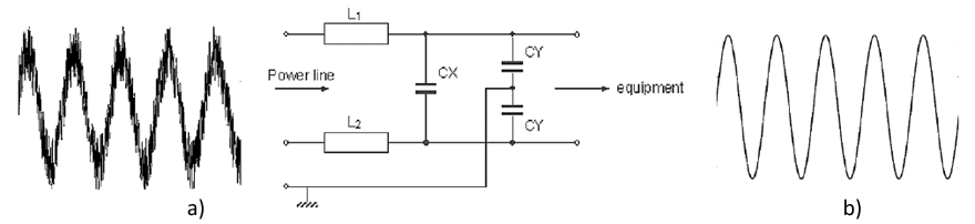
The safety EMI suppression capacitors, Class X and Class Y, are designed for AC line filtering, minimizing the generation of Electromagnetic Interference in the radio-frequency range and negative effects associated with received EMI/RFI in many electronic device applications. Class X and Y capacitors are directly connected to the AC power input in order to filter the noise emitted by the device to the electrical grid or to the power line. Because of the direct connection to the AC voltage, the capacitors may be subjected to overvoltage or voltage transients like lightning strikes and power surges. Class X capacitors are connected between line to line or line to neutral and Y capacitors are connected between line to ground. If a class X capacitor fails because of an overvoltage event, it is likely to fail short and this failure, in turn, would cause an overcurrent protective device, like a fuse or circuit breaker, to open. Therefore, a capacitor failing in this fashion would not cause any electrical shock hazards. If a Class Y “line to ground capacitor” fails short and this could lead to a fatal electric shock due to loss of the ground connection. For that reason, the class Y is designed to fail open in order to avoid a fatal electric shock hazard.

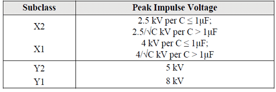
Class X capacitors can be further divided in two subclasses X1 and X2 according to the peak voltage of the impulse to which they may be subjected and which they can safely withstand. The X2 class capacitors can withstand peak impulse voltages up to 2.5 kV and X1 can withstand up to 4 kV. Similarly, class Y capacitors are divided into two subclasses Y1 and Y2, where Y2 capacitor can withstand max peak impulse voltages up to 5 kV and Y1 can withstand up to 8 kV. Also, X1 capacitors going to their higher peak impulse voltage capability can be substituted by Y2 or Y1 capacitors of the same or higher rated voltage whereas X2 capacitors can be substituted with X1, Y2 or Y1 capacitors of the same or higher rated voltage.

Metallized film capacitors in DC-Link applications
On the other hand, DC-Link capacitors form an essential stage in power conversion for many applications, including three-phase Pulse Width Modulation (PWM) inverters, photovoltaic and wind power inverters, industrial motor drives, automotive onboard chargers and inverters, medical equipment power supplies, etc. Demanding applications possess cost, harsh environmental, and stringent reliability constraints. Although circuit designs can use different approaches, the long-standing core of power conversion designs includes DC-Link capacitors. DC-Link capacitors can improve system energy density and resolve the challenge of ripple current introduced by rapid switching that is inherent to switching power conversions.
The automotive industry includes prime examples of power conversion in the hybrid and electric powertrains. Battery electric vehicles include a rechargeable bank of batteries to store energy for the drive system, an electric drive motor, and a power controller that includes an inverter. These all operate at high voltages extending from 48 VDC to as high as 800 VDC. Due to the physical limitations that limit current, high voltage correlates to high performance. The higher the operating DC voltage, the lower the required current flow for the same power output (P=VI). The automotive industry is well-known for requiring components that can operate with high reliability at extremely high temperatures, under continuous vibration, and where components are subject to harsh environmental conditions. The three-stage traction inverter converts battery power to drive the motor, and the DC-Link capacitor is key to this design.
MINIATURIZATION CHALLENGES
MINIATURIZATION CHALLENGES. FAILURE CAUSES AND FAILURE MODE MECHANISMS
In the latest film technology developments, manufacturers of film capacitors are trying to achieve excellent protection of film elements by utilizing new advanced humidity protective coatings, metallization treatments and improving the overall capacitor manufacturing processes. In this way, products could withstand severe operating conditions that would otherwise lower their reliability and performance. However, enhancing the reliability levels under high temperature, humidity, and bias (THB) conditions in miniaturized capacitors, for both DC and AC applications, can be particularly challenging [1-7].
Self-healing phenomena
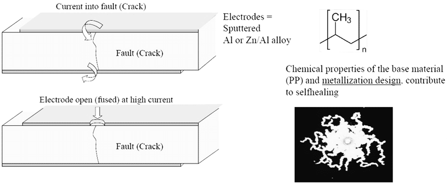
The self-healing property of metallized film dielectrics is the ability to recover from an internal drop of an insulation resistance. This property ensures a safe failure mode in AC frequency applications where electrical noise and peak voltages are added repeatedly or occasionally to the fundamental signal. So, when the self-healing operates the temporary break down which results in a clearing of a small area causing a minor loss of capacitance and a restoration of the capacitors’ initial electrical properties. In the metallized film capacitors, the metallized area is very thin and in case of dielectric break down the energy released by the arc discharge in the break down channel is sufficient to totally evaporate the thin metal coating close to the channel which results in a restoration of insulation and a small capacitance drop which can be between 1÷2 %. This property makes film capacitors highly suitable technology for safety applications.
Table 2 presents a comparison of different film dielectrics properties like Polypropylene (PP), Polyethylene Terephthalate (PET), Polyphenylene Sulfide (PPS) and Polyethylene Naphtholate (PEN) highlighting the main advantages, disadvantages and characteristics of each of these dielectrics and showing the suitability for different applications.

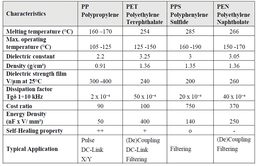
As this article concerns mainly applications with suppression and DC-link power box capacitors, it can be highlighted that the polypropylene is the most suitable dielectric due to its internal structure and its excellent self-healing property, shown in Figure 2.
Metallized polypropylene film technology is currently the main solution for EMI suppression and DC-link capacitors due to its excellent high voltage per micron and ultra-low, stable dissipation factor capabilities. Perhaps most importantly, it also has the best self-healing properties compared to other film dielectric technologies. However, combining high temperature and humidity conditions often has a drastic effect on the metallized polypropylene material when an AC or DC voltage is applied, resulting in accelerated degradation and potentially catastrophic failures of the capacitors. The root causes for this failure mode can be due to atmospheric corrosion or oxidation, corona effect and electrochemical corrosion of the metallization.

Mechanism of Atmospheric Corrosion or Oxidation Phenomenon
An oxidation or atmospheric corrosion of metal electrode alloys is mainly caused by the chemical destruction of metals due to the presence of H2O, O2 and corrosive media. Taking zinc electrode as an example, zinc reacts with oxygen and moisture in the environment at a very fast rate to form hydroxides and oxides. The corrosion reaction of zinc can be expressed by the following chemical reactions:

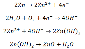
(1)
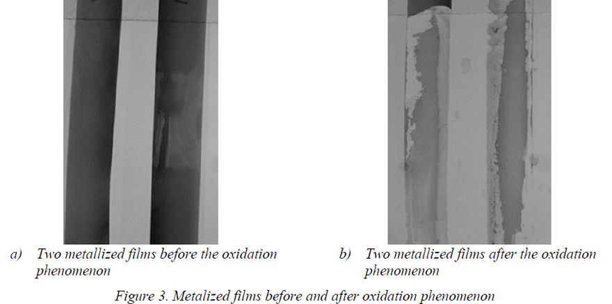
Atmospheric corrosion is often related to the ingress of atmospheric moisture and requires the presence of water and usually progresses from the ends of the capacitor cylinder in an axial direction toward the middle. Figure 3 shows the conditions of two metallized films before and after the oxidation phenomenon.

The converted metal in its oxidized state is not enable electronically conducting, leading to loss of capacitance in the areas affected. This process is active, without the voltage being applied, but its magnitude in encapsulated capacitors is most often negligible as the reaction rate is limited by diffusion of oxygen into the part and is strongly limited by the compact film winding and the thermosetting resin encapsulation.
Partial discharges or corona effect phenomenon
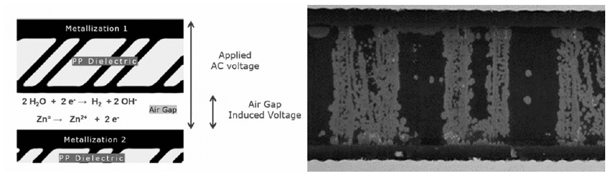
The term partial discharge is used to describe a localized dielectric breakdown of a small portion of a solid or fluid electrical insulation system under high voltage stress that does not completely bridge the gap between the electrodes, for example discharges occurring within solid insulation systems with gaseous voids. In film capacitors, there are small air gaps inside the film windings at which partial discharge may easily occur under high electric field and it can lead to dielectric degradation. The discharge can take place in the air gap in series to the film layer or in the air surrounding the active layers. Sometimes called ‘corona,’ this is the breakdown of micro-voids in the bulk of the dielectric material or air gaps between insulating layers. The effect is to insert a ‘partial’ short circuit into the insulation, effectively shortening the insulating path and locally reducing the breakdown threshold voltage. Each short places an extra stress on the remaining insulation, and as they accumulate over time, a tipping point is reached, and total breakdown occurs.
The film capacitors operating at mains voltage can suffer progressive loss of capacitance as corona discharges cause local vaporization of the metallization. The observed loss of capacitance is caused by ionization / corona, i.e. the air enclosed by the coil becomes ionized and this makes it more conductive. This means in turn that partial discharges on the metallized film surface can occur, causing damage to the metallized layer. The potential difference between two points on the film surface creates a small arc which vaporizes the metallization over a small area. There is a small capacitance loss, which after many such events becomes measurable. The behavior with respect to ionization is affected by ambient climatic conditions such as humidity and temperature. The potential difference decreases with temperature because the air pressure is lower at low temperature, therefore making it more likely to have ions or electrons oriented in the field direction for the discharge mechanism. The potential difference decreases with the humidity level because the dielectric strength of humid air is lower than dry air. This phenomenon can be limited using a minimum dielectric thickness and protecting the film internal element from humidity, with good enclosure materials as box and resin.

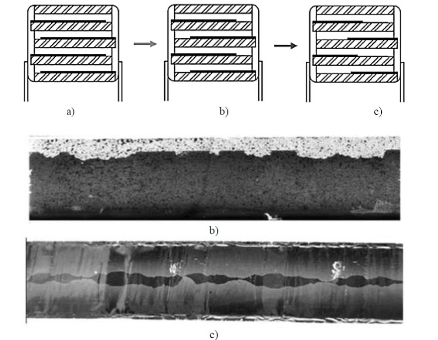
Due to geometrical factors, in single-metallized film construction, the corona effect usually starts very near to the armatures edge, in the free margin area. This is due to the fact that, in that zone, the electric field magnitude increases due to the tip effect. In Figure 4, two films where the corona effect has occurred are shown. During the corona effect, high temperatures are reached in proximity of the electrodes and the metallization is vaporized. Therefore, the active area is progressively reduced in size with a corresponding capacitance drop. It is easily observable that the two films start de-metallizing from the metallization edge, close to the free margin, on both sides. If the voltage is kept higher than partial discharge extinction voltage, the erosion will continue until the electrodes are eroded so that they are not overlapped anymore.
Mechanism of Electrochemical Corrosion
Electrochemical corrosion is an electrochemical reaction at the interface between metal and electrolyte. The reaction is a combination of an anode reaction and a cathode reaction forming circuit by ionic flow in electrolyte and electron flow in metal. Taking aluminum electrode as an example, the corrosion reaction of aluminum can be expressed by:

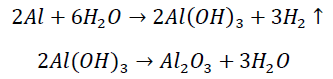
(2)
Aluminum or zinc aluminum alloys with an oxide layer on the surface may suffer electrochemical corrosion. Especially when the surface of the oxide layer has defects such as scratches, cracks, impurities or alloy phases, intergranular precipitation, local corrosion is more likely to be induced. The local corrosion is likely to expose the base metal, because the metal is in the active state (constitutes the anode), and the undamaged oxide layer is in the passive state (constitutes the cathode), thus forming an active-passive corrosion battery, so that the corrosion can be produced.
In the area of the electrochemical reaction, there will always be a certain amount of moisture in the polypropylene, and the moisture in the external environment will also penetrate inside of the capacitor. Since the electrode potential of aluminum is very low (the standard electrode potential of aluminum is -1.662 V), the free energy of forming Al2O3 is negative. Therefore, a certain amount of alumina must exist at the interface between polypropylene and aluminum. If the gap between the alumina and film layers is small enough, the water will form an electrolyte, connecting the alumina to the polypropylene and then forming an electrical double layer at the Al2O3/electrolyte and electrolyte/polypropylene interface.

In addition to the reduction of the capacitance, the corrosion of the metal electrode also increases the equivalent series resistance (ESR) of the capacitor and increases the dielectric loss. The main cause of the deterioration of the metallized film capacitor in the AC circuit is the decrease of the capacitance caused by electrochemical corrosion. The electrochemical corrosion rate of metallized film capacitor is affected by factors such as operating voltage, operating temperature, ambient humidity and electrode material.
STRESS TESTING & RELIABILITY
STRESS TESTING TO ASCERTAIN THE RELIABILITY
A well-accepted accelerated life test standard for active and passive components in the electronics industry is the Temperature-Humidity-Bias (THB) test, with levels of 85°C and 85% relative humidity under AC or DC bias conditions. For many years, designers in various industries (including automotive, energy, consumer, and industrial) have used this test to ascertain the reliability of their final products for up to 25 years of operation under severe climatic conditions. More recently, the THB test has been recognized as an IEC (International Electrotechnical Commission) standard for EMI suppression film capacitors.

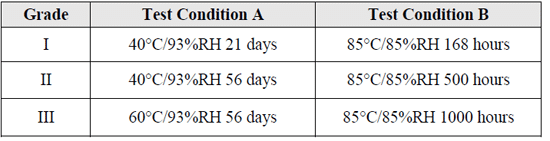

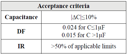
The suppression capacitor is usually a metallized film capacitor, defined as a safety capacitor that meet the requirements of IEC 60384-14. This standard incorporates seven groups of tests that cover standard capacitor properties: resistance to heat, vibration, mechanical shock and solvents, damp heat performance, impulse voltage endurance, charging and discharging properties, RF characteristics and passive/active flammability tests. THB test or Temperature, Humidity Bias test is a reliability test designed to accelerate the degradation process of a safety capacitor and measure the electrical parameters after a certain period of time if they are still within the specific limits which are defined as three different biased humidity grades I (A and B), II (A and B) and III (A and B) in the latest amendment AMD1:2016 of the standard IEC 60384-14, table 3, starting from mild up to harsh to ensure that the capacitors can meet the demanding harsh environmental and can continue to function during the whole product lifetime without having any issues. The acceptance criteria are listed in the table 4.

Designers needing to ensure that their products pass the THB evaluation and emission certification have encountered several challenges; for instance, it can be difficult to obtain the required technology and include multiple EMI suppression and DC-link capacitors into already component-dense circuits. There are also higher power requirements within a limited board space to take into consideration. The THB test ensures that the capacitance and dissipation factor are highly stable during the expected lifetime of the capacitors.
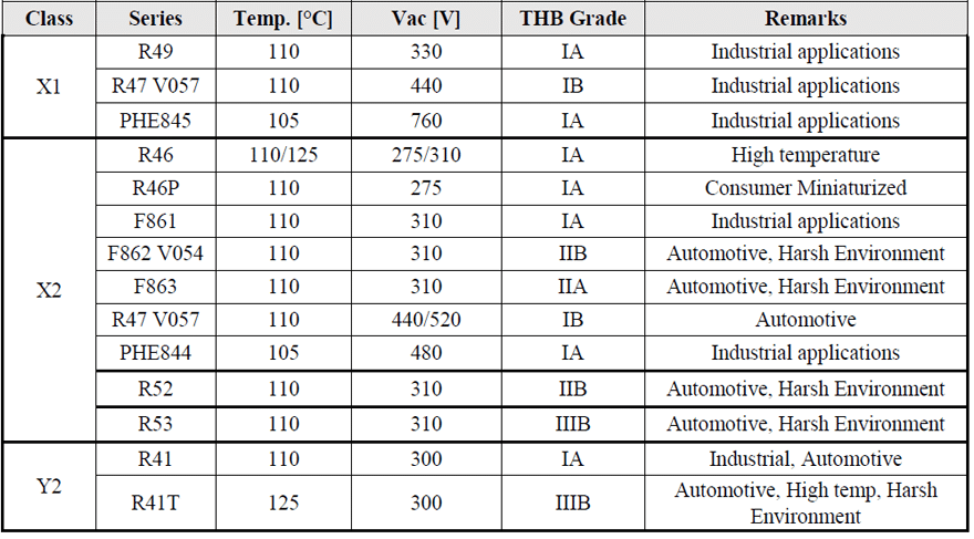
After going through the basic technical overview and requirements regarding the EMI suppression capacitors the next topic will be on the products in the KEMET portfolio. In Table 5 are listed the different types of X and Y capacitors available by the input voltage, temperature, THB grade and end applications.
In X1 class there are mainly R49, R47 and PHE845 series defined for different input AC voltages: 330, 440 and 760 Vac respectively. Similarly, in Y2 class there are R41 and R41T series being the highest temperature series with capability to withstand also higher DC voltages. In X2 class there are different series R46 with temperature capability up to 125°C and the R46P which is the miniaturized version of R46 suitable for commercial applications. The F862 V054 and F863 series are suitable for harsh environmental conditions and for automotive applications.
MINIATURIZATION CHALLENGES. DESIGN DETAILS
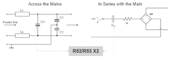
The EMI X2 capacitors are generally mounted in parallel with the mains, with the purpose of filtering electromagnetic interference, both from the mains and the equipment, and of protecting the appliance from voltage spikes. In this application, usually, the customers use capacitors with large nominal tolerance (+/-20%). In recent years high capacitance stability and low tolerance have become a key feature for X2 capacitors, due to the development of more and more applications in series to the mains, in which the capacitor itself has the role of feeding AC voltage to the circuit, via a capacitive divider. Besides the peak voltage withstanding capacitors have to be qualified, when used in series to the mains, for a high level of capacitance stability in order to feed the right AC voltage and power to the circuit through time. For these applications, besides the typical requirements for X2, the main challenge is the temperature-humidity-bias performances, considering different grades presented in the previous section.
The requirement of high capacitance stability should be considered during the design of these RFI capacitors, for example in the selection of film base, metallization resistance and all materials that give an enclosure of the internal film element. All these materials usually have special features that increase the cost of the capacitors. During the selection of suppressors, designers should require the real-application-requirement level of humidity withstanding capability, in order to find the right capacitor at the proper cost.
Metallized film capacitors, designed for harsh environmental conditions, are usually sealed with epoxy resin. The moisture ingresses to the interior of the capacitor through the sealing material, thus accelerating electrode corrosion [8]. As the water is continuously consumed during the chemical or electrochemical reaction, the reaction stops when the water is depleted. Therefore, the speed of external moisture ingress to the capacitor will significantly affect the corrosion rate of the electrode. The electrochemical reaction reduces the internal moisture concentration of the capacitor, so the external moisture will continue to diffuse into the capacitor through the epoxy and the gap.
In general, the film base material should have good self-healing capability, but also show a good behavior under tough humidity conditions: this means that some film base materials are not suitable at all for these applications. The metallization resistance selection has an important role in the right compromise between safety aspects and capacitance stability, like shown in figure 6. As previously stated, the higher the resistance value, the higher the performance on peak voltage withstanding, but the lower the capacitance stability in humidity conditions. Increasing the resistance, without modifying the morphological structure of the metal layer, means reducing the thickness of the metal that could be oxidized during the electrochemical corrosion phenomenon.

In the latest EMI suppression and DC-link power box film technology developments, KEMET is achieving excellent protection of film elements by utilizing new materials and improving the capacitor manufacturing processes. In this way, several products (see Table 5) can withstand severe operating conditions that would otherwise lower their reliability and performance. However, enhancing the reliability levels under high temperature, humidity, and bias (THB) conditions in miniaturized capacitors can be particularly challenging.
Some of the constraints of DC-link power box and EMI suppression capacitors correlate to the film quality and protection surrounding it. The amount and type of resin used, the epoxy filling the surrounding of the capacitor element, and the material and thickness of the radial box encapsulating them all play vital roles in a product’s reliability. Moreover, there is a mechanical challenge in manufacturing capacitors with smaller capacitance values; lower capacitances require less film and metallization material, making the product more susceptible to damage due to humidity.
EXPERIMENTATION, TEST RESULTS & CONCLUSION
EXPERIMENTATION AND TEST RESULTS
R52 and R53 new miniaturized X2 suppression capacitors’ design
KEMET’s R&D team has studied and experimented with unique solutions to address the challenges of designing EMI suppression capacitors that meet THB test requirements without sacrificing miniaturization and reliability. The first KEMET’s harsh environment solution was the F863, X2 series providing a compact and cost-driven solution for a consumer-oriented market. A few years later, followed the F862-V054, X2 series based on an enhanced metallized film technology that met the AEC-Q200 qualification for automotive applications.
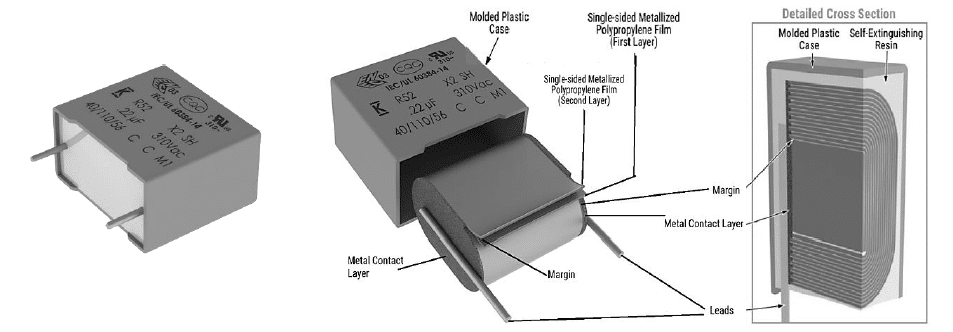
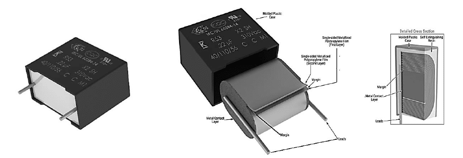
The latest EMI suppression solutions, presented in this paper, are the newest R52 and R53 designs (figure 7 and 8) with harsh environment capabilities, exceeding the performance of previous solutions and passing the latest IEC-60384-14 humidity robustness test with a Class IIB and Class IIIB classification, respectively. Those miniaturized designs are AEC-Q200 qualified and both are First to Market X2 technologies in terms of combined THB Grade IIB and IIIB level, miniaturized dimensions and the highest capacitance value.


KEMET’s R52 and R53 series space-saving X2 class capacitors are offered with capacitance values from 47 nF to 22 μF with lead spacing from 10 mm to 37.5 mm for R52 design and from 0.1 μF to 22 μF and lead spacing from 15 mm to 37.5 mm for R53 design, respectively. They offer the highest capacitance density for small footprint capacitors, enabling a smaller PCB area, reduced weight, lower costs, and improved reliability.
The capacitors are rated for 310Vac at 50 or 60 Hz and are intended for use in Class X2 line-to-line applications or in series with the AC mains (see figure 9). They are well-suited for applications that require high capacitance stability and current capabilities, e.g., power line communication (PLC) systems on smart-utility meters and consumer devices, making them ideal for converters in on-board and off-board chargers for electromotive vehicles (xEVs), smart grid hardware, solar inverters, EMI filtering in variable frequency motor drives (VFD) and LED drives, and in high energy density applications such as capacitive power supplies.

The R52 and R53 series features a metallized polypropylene film encapsulated in a self-extinguishing resin and a shell that meets UL 94 V-0 requirements. The metallized polypropylene film combined with an internal parallel construction provides self-healing properties to prevent catastrophic failure and extend service life. The capacitors are AEC-Q200 qualified and designed for harsh environments.
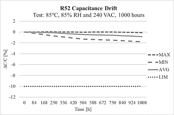
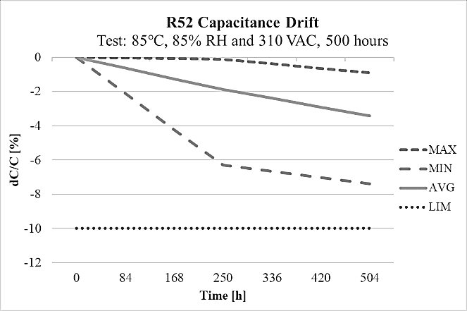
The R52 design has high capacitance stability after 1000 hours on the THB test at 85°C and 85% relative humidity environment at 240Vac, as it is shown on figure 10 and it also meets THB Grade IIB accelerated life testing requirements, with testing for 500 hours at rated voltage 310Vac in an 85°C and 85% relative humidity environment, with the capacitance drift presented on figure 11.


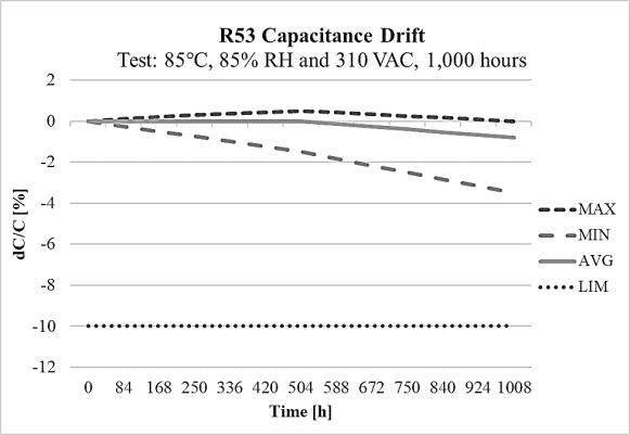
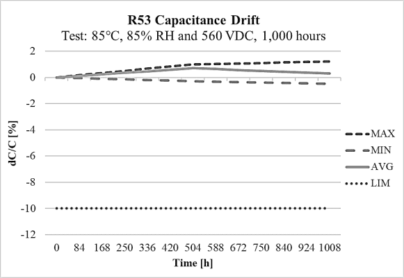
On the other side, the R53 design meets THB Grade IIIB accelerated life testing requirements, with testing for 1000 hours at rated voltage 310Vac and 560Vdc in an 85°C and 85% relative humidity environment, with the capacitance drift shown on Figure 12 and Figure 13 at 310Vac and 560Vdc respectively. Both designs R52 and R53 are rated for operation from -40°C to +110°C. They are also 100% factory screened at 1,900Vdc, with all electrical characteristics verified aftertesting. The R52 and R53 series successfully pass stringent tests while also providing a solution for space-constrainedapplications like automotive, 5G communications, servers and more.


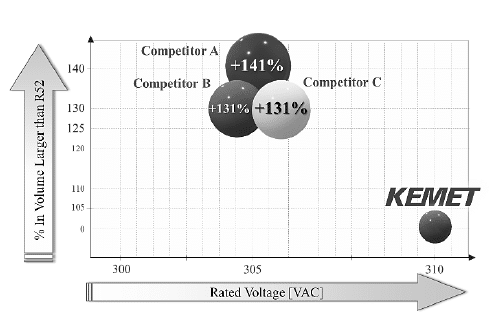
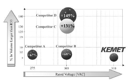
On the figure 14 and 15 is present a comparison of KEMET’s R52 and R53 design respectively, with the one of the competitors’ EMI solutions using a particular capacitance of 1.5 μF and lead spacing of 22.5 mm. On average, the R52 and R53 physical volume is 60% smaller than any other X2 solution with the same range of capacitance values present in the market.


The R52 and R53 technology reaches capacitance levels of 10μF, 15μF, and 22 μF. The high capacitance and current capabilities of KEMET’s R52 and R53 allow it to function as an excellent EMI suppression solution both across and in series with the mains on high energy density designs requiring a high level of filtering capability on a broad spectrum of frequencies. A good example is in variable frequency drives and EV fast-charging systems where designers prefer to utilize high-capacitance, certified EMI suppression capacitors together with AC and DC filtering solutions to mitigate harmonic content on the output of the drives and converters. The R52 and R53 are also suited for use in capacitive power supplies and power line communication systems.
The C4AU new DC-link power box film capacitor’s design
The DC-link power box capacitor is an important part of any power conversion module. Its input is usually the output of a rectifier stage or a DC-DC stage. Its output is either an AC or pulse width modulation (PWM) signal for drive systems or could even be the input for buck-boost convertors (see Figure 16).

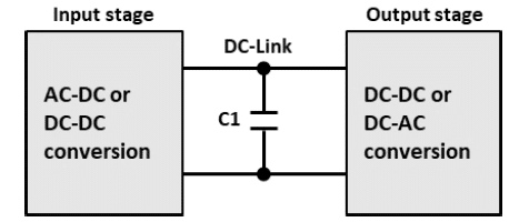
The DC-link power box capacitor is used for that intermediate point between the two conversion stages. The main purpose for the DC-link power box is to provide a low impedance path for high frequency switching currents which translates to ripple current which is a very common associated with the DC-link power box capacitors and of course to store the supplied energy when needed. DC-link capacitors need to be stable over temperature, frequency, and time. They have high capacitance density, low leakage current, low losses (dissipation factor), excellent self-healing capability, long operational lifetimes and they are able to withstand high power, high ripple current, high rated voltages up to 1200 Vdc, a large amount of charge/discharge cycles and for some specific applications they must operate reliably and safely in harsh environments.

The C4AU DC-link power box capacitor with a miniaturized size is a polypropylene metallized film capacitor with a rectangular, plastic box-type design filled with resin and uses 2 or 4 tinned copper wires. Automotive grade devices meet the demanding Automotive Electronics Council’s AEC-Q200 qualification requirements. Typical applications include DC filtering, DC-link, power electronics, IGBT snubbers, energy storage, renewable energy grid interface, motor drives, and automotive applications.
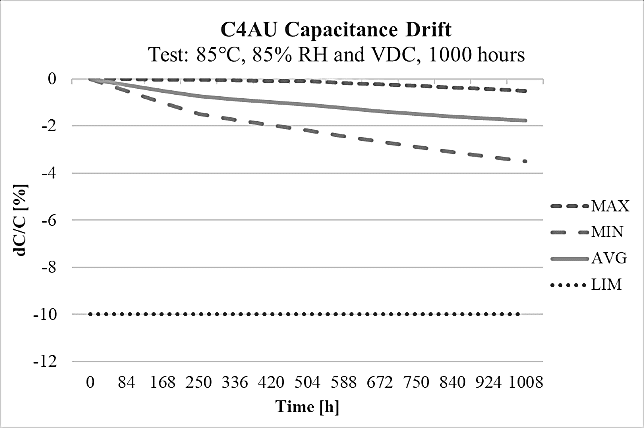
The most significant benefits of C4AU are the following properties: high capacitance density of 200 V/μm at 85°C, good self-healing, low loss, high ripple current, high contact reliability suitable harsh environmental conditions for high frequency applications and automotive grades (AEC-Q200). The C4AU technology reaches capacitance levels of 200 μF designed for DC rated voltage range 500÷1200V at maximum operating temperature of 105°C, with short lifetime of 200 h at 125°C and covering the pitch range starting from 27.5mm up to 52.5mm. This series is designed to withstand harsh environmental conditions at 85°C and 85%R.H. for 1000 h at rated DC voltage, showing the highest humidity robustness performance THB Grade IIIB with the capacitance drift shown on the Figure 17. The miniaturized size is providing an advantage of 28% reduction in dimension volume values compared with the actual C4AQ DC-link power box series, present in the KEMET portfolio that means 15% improvement on the PCB space reduction. Moreover, this new advanced technology design of C4AU with miniaturized dimensions has 320% increase in dV/dt.
CONCLUSION
KEMET’s new space-saving film capacitor’s designs, the C4AU DC-link power box and the R52 and R53 EMI X2 suppression capacitors are first-to-market solutions that meet the needs of today’s most challenging applications. Extensively tested for high reliability in harsh environments, the new KEMET’s miniaturized products offer an ultra-high capacitance in a compact package for more board savings and lower application costs for engineers. The entire package of C4AU, R52 and R53 new KEMET film capacitors provide the full capacitance solution with an optimal balance of miniaturization and reliability in automotive, industrial, consumer, and energy applications in any harsh environment.
REFERENCES
[1]J.H. Tortai, A. Denat, N. Bonifaci, “Self-healing of capacitors with metallized film technology: experimentalobservations and theoretical model”, J. Electrost., vol.53, pp.159–169, August 2001
[2]H. Li, P. Lewin, J. C. Fothergill. “Aging mechanisms of X2 metallized film capacitors in a high temperature andhumidity environment.” IEEE International Conference on Dielectrics, pp.804-807, July 2016
[3]M Michelazzi et al., “RFI X2 capacitors for high humidity environment”, CARTS International, 2014
[4]P.L Lewin,. J.C. Fothergill, S.J. Dodd. “Electro-chemical degradation of thin film X2 safety capacitors.” ElectricalInsulation Conference (EIC) IEEE, June, 2015.
[5]R.J. Van Brunt., “Physics and chemistry of partial discharge and corona. Recent advances and future challenges”,Dielectrics and Electrical Insulation, IEEE Transactions on, 1(5): 761-784, 1994
[6]X. Zhang “Corrosion and Electrochemistry of Zinc.” BeiJing: Metalworking Industry Press, 2008.
[7]Q. Chen et al., “Moisture Ingress of Metallized Film Capacitor under High Temperature and Different HumidityCondition”, IEEE Conference on Electrical Insulation and Dielectric Phenomena – Cancun – Mexico, pp.422-425,2018
[8]O. Hölck, “Transport of moisture at epoxy–SiO2 interfaces investigated by molecular modeling.” MicroelectronicsReliability vol. 53(8), pp.1111-1116, Aug., 2013

