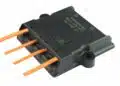



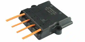







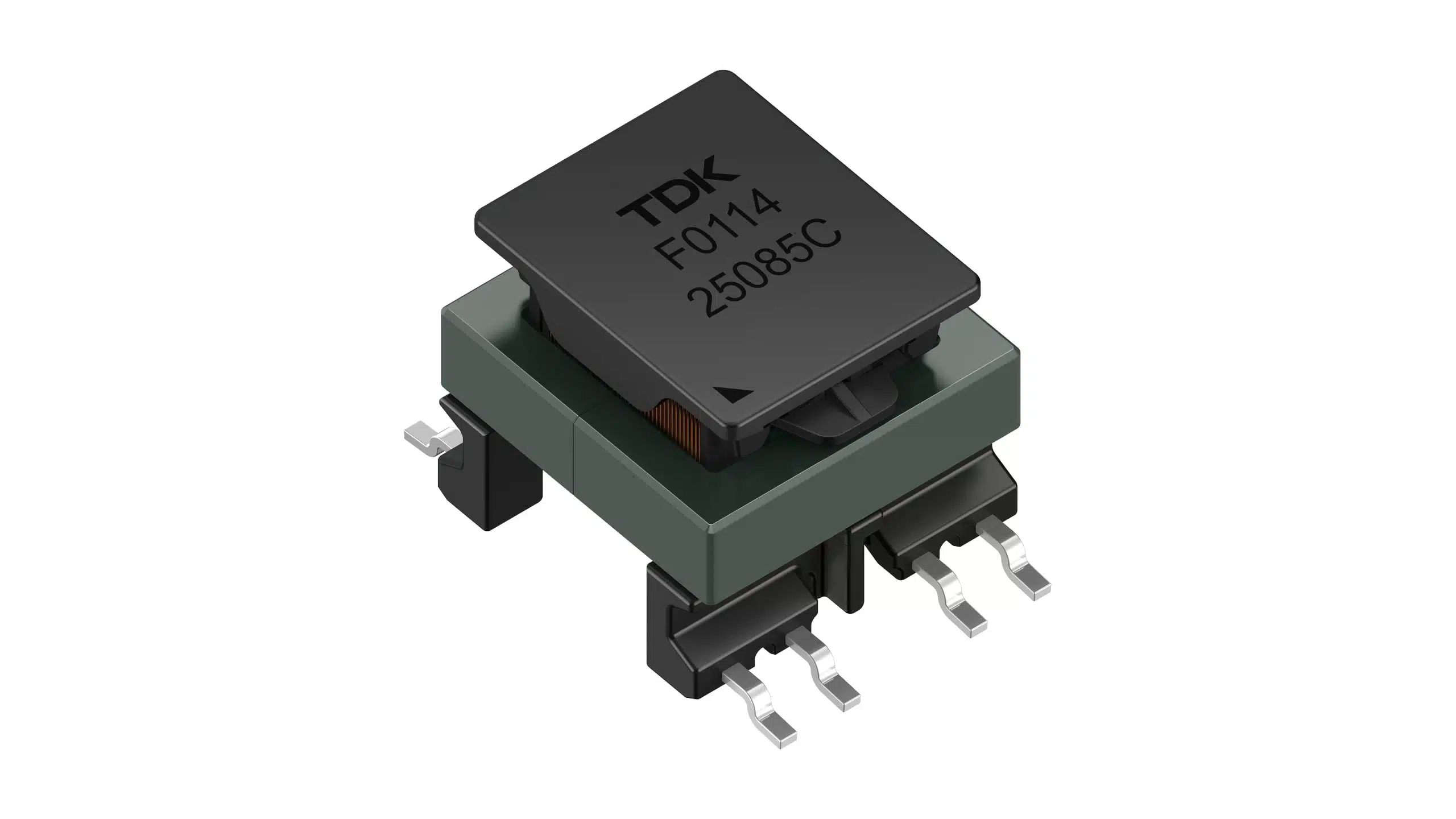
The new E13 EM surface‑mount transformer series from TDK targets 500 V automotive battery systems with compact footprints, automotive qualification and insulation systems aligned with relevant IEC standards, making them interesting for both traction and auxiliary power designs.
Gate drive transformers are a key building block in high‑voltage xEV traction inverters and isolated DC‑DC converters, where they provide galvanic isolation for IGBT/MOSFET drivers and auxiliary power stages.
Key features and benefits
- Compact SMD form factor with approximately 18.6 x 14.6 mm footprint and up to 12 mm height, helping reduce PCB area compared to through‑hole gate drive transformers in densely packed inverter and DC‑DC converter boards.
- MnZn ferrite core design optimized for typical switching frequencies between 100 kHz and 400 kHz, suitable for modern fast‑switching power semiconductors in flyback and push‑pull topologies.
- Wide inductance range from about 1.8 µH up to 240 µH according to manufacturer datasheet, allowing adaptation to different gate driver and auxiliary converter architectures without changing the mechanical envelope.
- Saturation current capability up to 9 A in selected variants, supporting robust operation under transient gate‑drive pulses and auxiliary supply loading.
- Low leakage inductance and optimized winding structure for stable signal transmission, reduced ringing and improved efficiency in high dv/dt environments typical of xEV traction stages.
- Advanced insulation system designed for basic insulation at 500 V DC and reinforced insulation at 300 V RMS (OVC II), helping designers meet creepage, clearance and transient overvoltage requirements in high‑voltage automotive battery packs.
- Automotive‑grade qualification to AEC‑Q200 Rev. E and a wide operating temperature range from -40 °C to +150 °C, matching typical automotive mission profiles including under‑hood and inverter‑mounted locations.
- Reflow‑solderable SMD package compatible with lead‑free reflow soldering according to JEDEC J‑STD‑020F and RoHS‑compliant construction, simplifying assembly and regulatory compliance in automotive electronics production.
Typical applications
The E13 EM series is targeted at isolated power conversion and gate drive tasks in electrified vehicles and related systems.
- Traction inverter gate drivers in battery electric vehicles and plug‑in hybrids, providing isolated drive signals for IGBTs or MOSFETs in 500 V battery systems.
- Isolated auxiliary DC‑DC converters in xEV platforms (for example 500 V to 12 V or 48 V supplies), using flyback or push‑pull topologies for on‑board power distribution.
- AC‑DC power supplies with isolation requirements aligned to IEC 60664‑1 and IEC 61558‑2‑16, where compact SMD transformers help reduce height and improve manufacturability.
- Auxiliary power systems in xEVs such as on‑board chargers, DC‑DC modules for auxiliary loads and low‑power inverter support circuits needing reliable isolation and automotive qualification.
In practice, these transformers fit into gate driver stages between the control ASIC/MCU and the high‑side or low‑side switches, as well as in small isolated supplies distributed across an xEV power electronics stack.
Technical highlights
Insulation and standards
The insulation system is central to high‑voltage automotive qualification and compliance:
- Insulation is designed to be compliant with IEC 60664‑1 (insulation coordination for equipment within low‑voltage systems) and IEC 61558‑2‑16 (requirements for switch‑mode power supply transformers).
- The series offers basic insulation for 500 V DC working voltage and reinforced insulation for 300 V RMS in overvoltage category II, supporting typical battery pack and grid‑connected auxiliary supply scenarios.
- Creepage distances up to 6.3 mm and clearance distances up to 5.5 mm are implemented within the SMD footprint, helping designers meet PCB layout requirements in compact inverter and DC‑DC designs without resorting to larger through‑hole parts.
- The transformers are specified for transient overvoltages up to 2500 V and a partial discharge extinction voltage of 900 V, supporting robust operation under surge and switching stress typical for xEV traction environments.
For design engineers, this means the E13 EM series can form part of the isolation barrier without extensive additional spacing or custom mechanical structures, provided PCB design maintains equivalent creepage and clearance.
Electrical parameters and operating range
From the key data, the following technical highlights can be extracted:
- Typical operating frequency range covers roughly 100 kHz to 400 kHz for flyback versions, aligning with many modern gate driver and auxiliary converter switching frequencies.
- Inductance values span from approximately 1.8 µH to at least 240 µH depending on variant, allowing selection for gate drive pulse shaping versus auxiliary power energy storage according to manufacturer datasheet.
- Saturation currents reach up to 9 A on selected flyback variant, supporting robust magnetization under peak gate drive or auxiliary supply pulses.
- Different turns ratios (for example 1:1, 1:2:2 or 1:3.78:1.55) are available to support voltage scaling and multi‑winding configurations in isolated gate drivers and push‑pull supplies.
The use of MnZn ferrite cores supports low loss at the given switching frequencies, while the SMD package balances electrical performance with automated assembly.
Mechanical and environmental characteristics
- Approximate footprint of 18.6 x 14.6 mm and maximum height of about 12 mm provide a compact transformer solution for high‑density layouts.
- Operating temperature from -40 °C to +150 °C covers typical automotive extended temperature ranges including exposure near power modules and under‑hood installation.
- Automotive qualification to AEC‑Q200 Rev. E indicates the series has passed standard passive component stress tests (thermal cycling, mechanical shock, vibration, etc.) expected by automotive tier‑1 and OEM customers.
These mechanical and environmental characteristics make the E13 EM series suitable for designs where board space is limited and temperature extremes are expected.
Selected variants and key parameters
The press release lists several ordering codes covering both flyback and push‑pull topologies. The following table summarizes the key relationships between topology, turns ratio, inductance and saturation current according to manufacturer data.
| Ordering code | Topology | Turns ratio (N) | Inductance LN1 (µH) | Saturation current ISAT (A) | Frequency range (kHz) |
|---|---|---|---|---|---|
| B82802F0007A213 | Flyback | 1:1:0.5 (N1+N2:N3:N4) | 30 ±10% (N1+N2) | 2 | 100 – 400 |
| B82802F0004A213 | Flyback | 1:2:2 (N1:N2:N3) | 14.4 ±15% | 1.6 | according to datasheet |
| B82802F0005A113 | Flyback | 1:1 (N1:N2) | 1.8 ±10% | 9 | according to datasheet |
| B82804F0503A200 | Push‑pull | 1:3.78:1.55 (N1:N2:N3) | ≥ 50 | according to datasheet | according to datasheet |
| B82804F0114A200 | Push‑pull | 1:1:1.5:1.5 (N1:N2:N3:N4) | ≥ 110 | according to datasheet | according to datasheet |
| B82804F0244A210 | Push‑pull | 1:1:1 (N1:N2:N3) | ≥ 240 | according to datasheet | according to datasheet |
For detailed winding data, exact inductance distribution per winding and full frequency derating, designers should consult the corresponding transformer datasheet pages.
Design‑in notes for engineers
- Topology matching: Select flyback variants for simple isolated auxiliary supplies and certain gate driver circuits, and push‑pull variants for higher‑power or more symmetric isolated supplies where transformer utilization is higher.
- Turns ratio selection: Use turns ratio to set isolated gate drive voltage or auxiliary supply output. For example, 1:2:2 variants allow step‑up voltage generation and dual‑output configurations, while 1:1 variants are suited to level‑shift applications with minimal voltage transformation.
- Inductance and ISAT sizing: Choose inductance values and saturation currents in line with calculated magnetizing current and required energy storage. Lower inductance and higher ISAT will favor short, high‑current pulses typical in gate drive transformers, while higher inductance suits auxiliary power transfer.
- Frequency planning: Keep operating frequency within the typical 100 kHz to 400 kHz envelope for flyback types, and confirm recommended ranges for push‑pull variants in the datasheet to minimize core loss and ensure acceptable temperature rise.
- Creepage and clearance layout: Although the components offer up to 6.3 mm creepage and 5.5 mm clearance internally, PCB layout must maintain equivalent distances between primary and secondary circuitry, including copper pours and adjacent components, to preserve insulation coordination.
- Thermal management: In compact traction inverters and DC‑DC modules, carefully consider thermal coupling between these transformers and nearby power devices. Use realistic thermal models and derating curves from datasheets to ensure operation within the -40 °C to +150 °C specification over the vehicle duty cycle.
- Assembly and reliability: The SMD form factor and JEDEC‑compliant reflow capability allow integration into standard SMT lines. Still, designers should review recommended solder pad layouts and reflow profiles from TDK documentation to avoid solder voids and mechanical stress on the ferrite core and windings.
As a practical example, in a 500 V battery traction inverter using isolated gate drivers, a designer could choose a 1:1 gate drive transformer variant with sufficient ISAT to deliver short high‑current gate pulses, place it between the driver IC and the IGBT module, and rely on the integrated insulation system to meet standards without significantly increasing board area.
Source
This article is based on technical information provided in the TDK Electronics press release on the E13 EM series of SMD gate drive transformers and associated official product documentation from the manufacturer.