
Molex’s new HSAutoLink G automotive Ethernet connector system targets the rapidly growing bandwidth needs in software‑defined vehicles, bringing multi‑gigabit performance up to 25 Gbps into a compact, USCAR‑compatible footprint.
Designed for ADAS, radar/LiDAR and zonal architectures, it gives OEMs and tier‑ones a field‑proven upgrade path with improved signal integrity, routing flexibility and sourcing optionality.
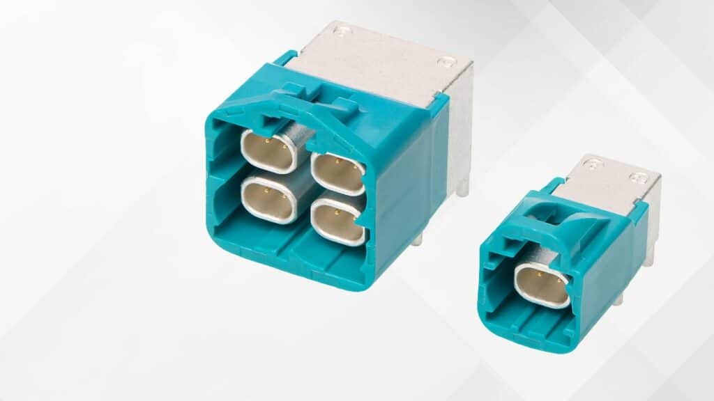
Key features and benefits
- Multi‑gigabit differential Ethernet links up to 25 Gbps supporting STP and UTP cabling for high‑bandwidth in‑vehicle networks such as ADAS, LiDAR, radar and central compute modules.
- USCAR‑compatible interface and footprint enabling drop‑in use within existing automotive Ethernet connector housings, simplifying mechanical packaging and reducing requalification effort in existing ECU designs.
- Compact form factor for space‑constrained modules helping reduce connector footprint and overall harness bulk in dense under‑dash and under‑hood environments.
- Advanced EMI shielding and controlled differential impedance to preserve signal integrity at high data rates in noisy automotive environments, reducing the risk of random communication errors and time‑consuming redesigns.
- Terminal anti‑stub feature for robust mating that protects contacts during plug‑in, reducing mis‑mating risk and improving long‑term reliability in harsh vibration conditions.
- Reversible housing shroud providing added flexibility for connector orientation and routing, which is particularly useful when optimizing harness layout in zonal architectures.
- Multiple, uniform ground‑contact points integrated to enhance EMI suppression and improve overall system EMC performance.
- Backed by a large installed base with more than 700 million HSAutoLink connectors and cables delivered since 2008, giving design teams confidence in long‑term availability and field reliability.
Typical applications
HSAutoLink G is clearly positioned for high‑speed data paths in modern vehicles where traditional CAN or LIN buses no longer provide sufficient bandwidth.
- Advanced Driver‑Assistance Systems (ADAS) sensor fusion ECUs aggregating camera, radar and ultrasound data.
- LiDAR and radar front‑end modules requiring deterministic, low‑latency, high‑data‑rate links to central processing units.
- Zonal architectures where each vehicle zone aggregates multiple sensors, actuators and local compute nodes over Ethernet.
- Central compute modules in software‑defined vehicles acting as the main hub for perception, path planning and infotainment.
- Immersive cockpit and display systems with high‑resolution multi‑screen outputs connected over automotive Ethernet.
- High‑speed transportation networking segments where 25G automotive Ethernet is gaining traction in fast‑moving markets such as China, and gradually in broader global applications.
From a passive‑components perspective, these high‑speed links impose stringent requirements on EMC, connector impedance control, and layout practices in the associated ECUs, making the shielding and grounding details of the connector family directly relevant for filter, choke and protection component selection in the same signal path.
Technical highlights
While the press release does not list a full parametric table, several technical characteristics are explicitly stated or implied. Key points are summarized below, with exact electrical limits to be confirmed in the manufacturer datasheet where required for design‑in.
Differential link and shielding concept
- Differential STP/UTP links up to 25 Gbps, aimed at multi‑gig automotive Ethernet.
- Controlled differential impedance, which in practice means the connector geometry and contact arrangement are tuned to match the target characteristic impedance of the Ethernet channel, minimizing reflections and eye‑diagram degradation.
- Advanced EMI shielding, supplemented by multiple uniform ground contacts intended to provide low‑impedance grounding paths and reduce common‑mode noise.
In practice, controlled impedance and shielding help keep insertion loss, return loss and crosstalk within tight budgets, especially when these connectors are part of longer channels combining twisted pairs, magnetics, common‑mode chokes and EMC protection devices.
Mechanical and interface characteristics
- USCAR‑compatible housing/interface, allowing integration into standardized automotive connector environments and enabling alternate sourcing strategies.
- Compact connector dimensions for reduced space and weight, supporting tight ECU packaging envelopes.
- Anti‑stubbing terminal design that protects contact interfaces during mating, addressing common failure modes in high‑volume automotive assembly and service.
- Reversible shroud design, offering symmetric mechanical options for orientation and cable routing.
Product family elements
- Family includes terminals, connectors, PCB headers and cables.
- Designed to fit within existing USCAR Ethernet interfaces so OEMs can qualify alternates without major mechanical redesign.
- Samples of HSAutoLink G are becoming available to enable early qualification and design‑in testing.
In a typical Ethernet ECU, the PCB header part mates to the harness connector; design engineers must consider the mechanical tolerances, keep‑out zones and board stack‑up to avoid compromising controlled impedance at the connector–PCB transition. Exact footprint and pad geometries are according to the manufacturer datasheet.
HSAutoLink family context
HSAutoLink G extends the established HSAutoLink, HSAutoLink II and HSAutoLink C family, which have long been used as rugged automotive high‑speed connectors. By moving the supported Ethernet data rate up to 25 Gbps, Molex aligns this connector generation with emerging SDV and autonomous mobility platforms where higher‑bandwidth links are essential.
HSAutoLink G vs earlier HSAutoLink families
HSAutoLink G presents an evolutionary step in an established connector family. The following table summarizes the positioning information; detailed parametric differences must be taken from series datasheets.
| Family | Target use case focus | Data rate positioning (press info) |
|---|---|---|
| HSAutoLink | Early high‑speed automotive connectivity, legacy ECUs | High‑speed links below current 25 Gbps tier |
| HSAutoLink II | Enhanced robustness and performance for newer platforms | Higher bandwidth than original, exact value according to datasheet |
| HSAutoLink C | Connectivity variants for specific transport networking | High‑speed Ethernet, details per datasheet |
| HSAutoLink G | Multi‑gig automotive Ethernet up to 25 Gbps and SDVs | Explicitly positioned at up to 25 Gbps |
This family overview helps purchasing and engineering teams understand that HSAutoLink G complements, rather than replaces, earlier series, which may remain suitable for lower‑bandwidth or legacy platforms.
Design‑in notes for engineers
From an ECU and harness design perspective, the connector choice interacts strongly with passive component selection, EMC compliance and overall system robustness. HSAutoLink G incorporates several features that simplify or constrain design decisions.
- Treat the connector as part of the controlled‑impedance channel. Layout of the PCB header, especially pad shapes and anti‑pad clearances in reference planes, must support the target differential impedance of the Ethernet pair; follow Molex’s recommended land patterns and keep differential via transitions as short and symmetric as possible.
- Coordinate shielding strategy with EMC filter design. The advanced EMI shielding and multiple ground contacts should tie into the ECU’s chassis or RF reference ground; consider where common‑mode chokes, surge protectors and ESD devices are placed relative to the connector to minimize parasitic inductance and improve ESD robustness.
- Account for USCAR interface constraints. Since the connector is USCAR‑compatible, mechanical envelope, locking features and latch forces are constrained; harness routing and strain relief must be designed so that vibration and thermal cycling do not compromise contact integrity.
- Leverage the anti‑stubbing feature but still design for assembly robustness. The protected contacts reduce mis‑mating, yet production lines should still implement visual alignment guides and poka‑yoke measures; in harsh environments or service situations, additional housing guidance features may be beneficial.
- Plan for reversible shroud usage. The reversible housing allows flexibility in connector orientation; use this to simplify routing around other passive components such as large inductors, common‑mode chokes and EMI filters, reducing congestion and potential coupling issues.
- Consider alternate sourcing strategies early. The USCAR‑compatible footprint is intended to facilitate multi‑source connector strategies. When qualifying alternates, pay close attention to subtle differences in shielding implementation and ground‑contact geometry, as these can affect EMC margins and the required performance of surrounding passive components.
- Align with 25 Gbps test methodologies. For channels targeting up to 25 Gbps, ensure that your validation strategy includes appropriate eye‑diagram, jitter and BER testing across temperature and voltage ranges; connector performance under these tests directly influences requirements for line termination networks and any passive equalization structures.
- Use manufacturer simulations and application notes. Molex references extensive real‑world simulations and reliability tests; where available, use these as a starting point rather than building models from scratch, especially when co‑optimizing connectors, cables and EMI filter networks.
In addition, coordination between mechanical, SI/EMC and procurement teams is recommended: connector series selection has implications on harness manufacturing capabilities, available EMI grommets and shielding practices, which in turn impact the passive component strategy for surge protection, line filtering and common‑mode suppression.
Source
This article is based on information published in Molex’s official press release announcing the HSAutoLink G automotive Ethernet connector system, complemented by related product family pages from the manufacturer website. Technical details are interpreted from that material; for exact ratings and parametric limits, please refer directly to the manufacturer datasheets and design guides.
References
- Molex press release: Molex Delivers Next‑Generation HSAutoLink G Automotive Ethernet Connector System
- Molex HSAutoLink G multi‑gigabit differential connectors – product family page
- Molex HSAutoLink, HSAutoLink II, HSAutoLink C – high‑speed transportation networking overview

