





Designers selecting cores for high‑frequency power inductors often face the choice between ferrite and nanocrystalline materials, with conflicting advice on how core type affects turns count, air‑gap and overall size.
This article summarizes and expands on a video presentation by Sam Ben‑Yaakov that explains this trade‑off, and clarifies how ferrite and nanocrystalline cores behave in gapped power inductors designed for energy storage at high frequency.
The focus is on practical implications for inductor design engineers and component buyers working with modern ferrite and tape‑wound nanocrystalline cores.
Key features and material properties
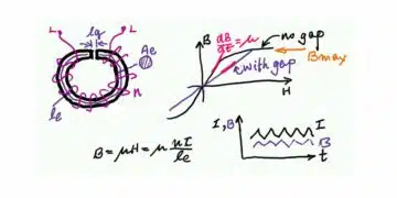
Toroidal power inductors with an air gap, used for energy storage in switching power converters, store most of their energy in the gap rather than in the magnetic core material. This is key to understanding how permeability and saturation relate to the core geometry.
Typical applications
Power inductors used in converters where the current contains a DC component plus superimposed ripple must be able to store magnetic energy. To achieve this, the core – whether ferrite or nanocrystalline – needs an intentional air gap in its magnetic path.
In these applications, typical use cases include:
- Energy‑storage inductors in DC‑DC converters, where inductance and peak current define energy storage requirements.
- PFC and boost inductors, operating at elevated ripple and switching frequencies with tight loss constraints.
- Output chokes in high‑frequency power supplies, where thermal design and core losses limit allowable ripple.
In all these cases, the limiting factor for maximum usable magnetic flux density is not always the intrinsic or of the core material. At high frequency and high ripple, the allowable may be set by acceptable loss and temperature rise rather than by saturation.
Toroidal inductor model with gap
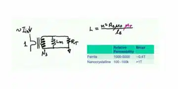
Inductance of a gapped toroidal core inductor with a uniform cross‑section area , magnetic path length , and an air gap of length with turns can be expressed asfor the ungapped case, where is the relative permeability of the core material. In a gapped inductor, the effective relative permeability is dominated by the geometry of the magnetic path and the gap:
This means the effective permeability is primarily a function of the ratio and becomes largely independent of the core material’s intrinsic once a significant air gap is introduced.
Substituting the geometry‑dependent permeability into the inductance expression leads to:
This shows that, for a gapped power inductor, inductance depends on the number of turns , the cross‑section area and the gap length , but not directly on the material’s intrinsic permeability.
Flux density, current and size relationship
Combining the inductor voltage‑current relation with Faraday’s law and the core geometry yields a key design relationship:
where the product depends on the required inductance, maximum current and the maximum allowable flux density in the core. This product directly relates to the physical size of the inductor: for given electrical requirements and material , higher allowable leading to a lower required implies that the inductor can be physically smaller.
In other words, for fixed inductance and current:
- If is higher (nanocrystalline), can be smaller.
- If is lower (ferrite), must be larger.
Summary of ferrite vs nanocrystalline behavior
The relevant differences for gapped power inductors can be summarized as:
| Aspect | Ferrite core | Nanocrystalline core |
|---|---|---|
| Relative permeability | – | |
| – | (typ. – | |
| Loss behavior | Moderate, frequency dependent | Can be lower at HF with thin tape |
| Core size implication | Larger for given | Smaller for given |
| Typical turns requirement | More turns | Fewer turns |
| Gap length trend | Wider gap | Narrower gap |
| Cost | Lower material cost | Higher cost for low‑loss thin tape[ |
From practical points:
- Nanocrystalline core: fewer turns and a narrower air gap.
- Ferrite core: more turns and a wider air gap.
- Nanocrystalline materials provide a much higher than ferrites.
- Higher allows a smaller for the same inductance and maximum current.
Therefore, for a given electrical specification, a nanocrystalline core can indeed be smaller than the corresponding ferrite core.
This is an important design‑in message: when space and weight are constrained, nanocrystalline cores can provide a compact solution, albeit with higher material cost and the need to manage losses at high frequency.
Loss‑limited versus saturation‑limited design
A key caveat in the presentation is that the limiting value of magnetic flux density in a practical design is not necessarily the material’s intrinsic or saturation point. At high switching frequencies and with high ripple current:
- Losses depend strongly on , the amplitude of the AC component of flux density.
- Thermal constraints often force designers to limit to avoid excessive core loss and temperature rise.
- As a result, the effective maximum usable in the design can be much lower than the material’s nominal .
In high‑frequency, high‑ripple applications, power inductors become loss‑limited rather than saturation‑limited. Even with nanocrystalline materials offering high , the practical benefit might be constrained by the allowable losses, especially if the tape thickness or insulation does not support very low eddy‑current losses.
For design engineers, this implies:
- Core selection should consider both material and detailed loss curves versus frequency and .
- Gap and turns must be chosen in combination to meet inductance, current and loss requirements, not just to avoid saturation.
- Datasheet loss information and thermal modelling are crucial inputs when exploiting nanocrystalline materials at high frequency.
Practical design hints
Based on the relationships discussed:
- When converting a ferrite‑based design to nanocrystalline for the same inductance and current, expect:
- Fewer turns.
- Shorter air gap.
- Potentially smaller cross‑section area , subject to loss constraints.
- When staying with ferrite in high‑frequency applications:
- You will typically need more turns and a wider gap to achieve the same inductance at lower
- Pay attention to core loss versus frequency, as different ferrite grades offer trade‑offs between loss and permeability.
- For nanocrystalline tape‑wound cores:
- Thin ribbon is beneficial for reducing eddy currents and losses but increases cost.
- Design choices should balance compact size, loss performance and cost, especially in volume production.
Conclusion
Sam Ben‑Yaakov’s presentation shows that effective permeability in energy‑storage inductors is governed primarily by geometry, not by the intrinsic of the core material once a significant gap is present. As a result, inductance depends on turns, cross‑section and gap length, while inductor size is linked to the product and the maximum usable flux density.
For design engineers, this leads to two clear conclusions: nanocrystalline cores require fewer turns and a narrower gap than ferrites for the same inductance and current, and they can be physically smaller thanks to higher , subject to loss limitations at high frequency. In practice, high‑frequency high‑ripple designs are often limited by core loss rather than saturation, making detailed loss data and thermal considerations essential when exploiting the advantages of nanocrystalline materials.
Source
This article is based on a technical video presentation by Sam Ben‑Yaakov discussing ferrite versus nanocrystalline inductor cores, with all quantitative statements according to the information presented and consistent with typical manufacturer datasheets.