
April 11th, 2018, by Tomas Zednicek, EPCI., Updated April 17th 2018
April 17th 2018 Update: Download this article also in white paper pdf and presentation pdf slides:
White paper pdf: 


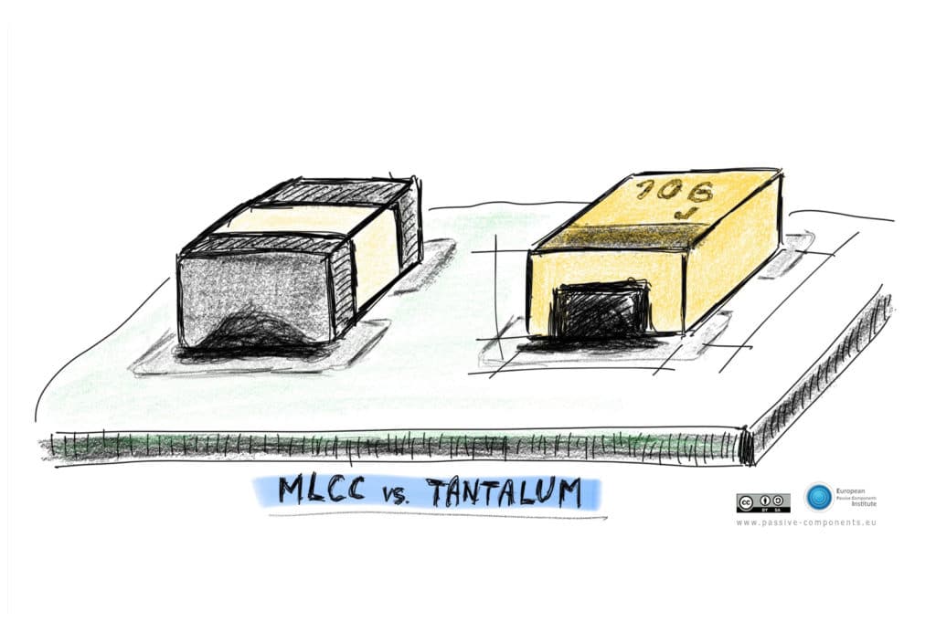
MLCC capacitor market is currently going through a tough supply time period. MLCC manufactures are leaving their low margin, high volume, consumer segment and concentrating on supply of higher added value parts. This is resulting in a considerable MLCC shortage that may take several years to be resolved. [1],[2],[3]. This may limit end electronic makers production and causing a serious market concerns with risks of line stop situations. Over the decades MLCCs Class II capacitors were replacing tantalum capacitors, mostly due to the price and availability reasons. It may be good to refresh some of the basic replacement guidelines from the opposite direction – replacing MLCC class II by tantalum and NbO capacitors – based on the current situation on the market to be ready and flexible.
MLCC current leadtimes on certain types may reach as long as 40 to 60 weeks !, and it remains tight in April [17], tantalum capacitors are getting tighter as well [16], nevertheless at the time of writing of this article it can still offer half of the leadtime on number of possible replacement parts. This also includes NbO capacitors, sister parts to tantalum capacitors, with many similar features and despite it occupies relatively small percentage of market, it should be included to the list of considered alternatives to provide wider flexibility and options.
1. Case Sizes and Pad Dimensions
MLCC and tantalum/NbO footprints and pad designs are compatible for at least the basic case sizes 0603, 0805, 1206 and 1210 thus, no board PCB pad re-design are necessary to considered in general. Nevertheless, some attention has to be paid to the component thickness (max height) for head to head replacement. The table below is showing some cross comparison of case sizes between MLCC and tantalum/NbO capacitors. Please note that the tantalum letter code may be manufacturer and series specific, especially in its low profile version.
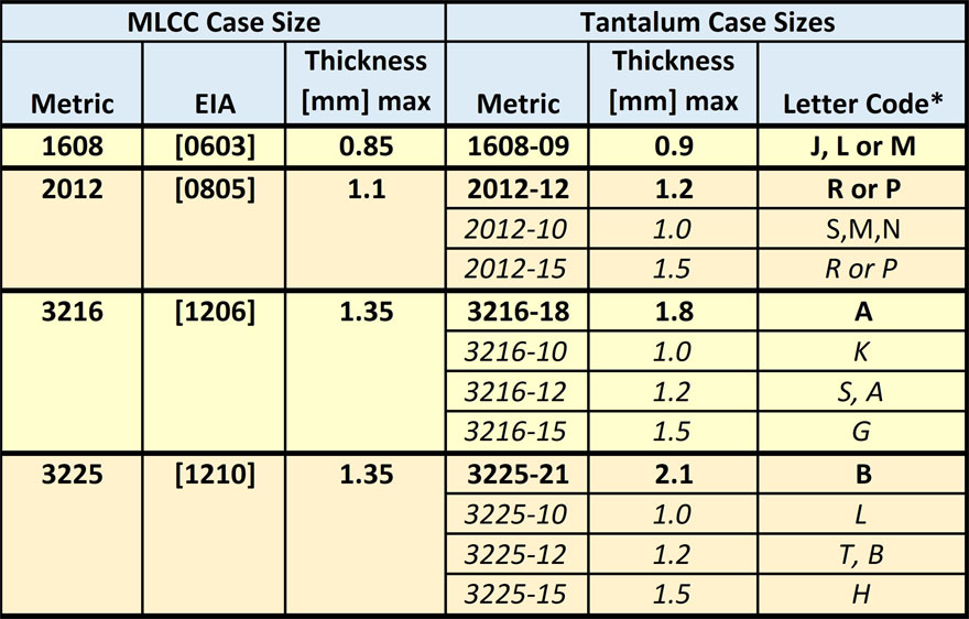
From the technology stand point, MLCCs are good in making parts physically smaller, tantalums answer better the needs for thin and flat designs. For example, if the task is to get maximum capacitance within 1.0mm max height, tantalum capacitors can make easier larger thin part with high capacitance in a mechanically strong body, unlike the MLCCs that could lead to a fragile design with risk of cracking. In reality, tantalum capacitors are available in more thickness and low profile case options as seen in Table 1. On the other hand, MLCC technology can go to much smaller dimensions and make smallest capacitors available. (not listed in the Table 1. as not relevant for this comparison).
Volumetric efficiency wise, X7R/X5R MLCCs are offering about a similar volumetric efficiency today as available by tantalum capacitors or one step higher values at smaller case sizes. Nevertheless MLCC “effective capacitance” in the real operation conditions shall be considered as the capacitance value decrease with DC and AC applied voltage compare to tantalum/NbO with stable rated capacitance value.
2. Cost Matters
In a “stable” market environment, technology based cost for 1206 case MLCC class II and Tantalum capacitors can be very close (depending on capacitance and voltage value). The 1206 case size is a cost down sweet-spot case size for a standard tantalum capacitors and it can be in price competitive position to MLCC class II.
MLCC capacitors are manufactured in process sheets that are cut into individual capacitors, its cost down way (with certain limits and specific product exceptions) is downsizing. Thus, smaller case sizes 0805 and 0603 may be cheaper than 1206, even with a more expensive high tech material used. (as there are more smaller units per one process sheet produced). This is not the case of tantalum/NbO capacitors, where a standard “in-row units” manufacturing technology processing of smaller case sizes below 1206 size is more expensive.
In consequence, 0805 and 0603 tantalum capacitors may be more expensive compare to the MLCC components. However, to be fair to tantalums, it is not that easy and simple rule, as tantalums are more stable without loss of capacitance with applied voltage, thus in some cases you may end up that the stable performance tantalum cap is a cheaper solution than a MLCC solution that looses capacitance with voltage and time … lets’ discuss this more in next chapters.
0402 and 0201 tantalum case sizes are also available on the market, but are considered as a niche applications with parameters, cost and mass volume capability too far from the MLCC high volume parts to be considered in this article. On the large case size scale, MLCC parts bigger than 1210 are also available, nevertheless the volume is much smaller due to the risk of cracking. Some companies are limiting MLCC max size in volume to 1210 case for this reason in addition.
The above discussed cost structure is however reflected to the capacitors pricing in “stable” market conditions. Today, when we are in a short supply situation, the main price driver is becoming “availability”. As a consequence, in example, MLCC prices are expected to rise 40-50% in 2Q18 according to Taiwan based Digitimes [15].
3. Key Advantages Overview
MLCC class II advantages
- low ESR
- high ripple current load
- non-polarized
- low DCL leakage current
Tantalum/NbO advantages
- no piezo noise
- stable capacitance with voltage BIAS and temperature
- high mechanical strength, robustness and vibration resistance
Common strong points
- lead-free standard design and reflow compatibility
- ROHS friendly standard design
- wide temperature range (-55/+125C ready as a standard)
- relatively very good basic reliability
- high capacitance in small dimensions
4. Manufacturing Technology Background Snapshot
MLCC class II capacitors are getting its high capacitance vs voltage value due to the high dielectric constant material (K) based on BaTiO2 ceramic. Such high K material is however linked with high losses and some other cons in parameter stability – mainly the capacitance drop with applied voltage and temperature, generation of hearable noise (piezo effect) during mechanical vibrations while voltage is present.

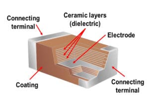
The internal structure of high CV MLCC capacitor, as shown in Fig.1., is made of houndreds to thousands of conductive electrodes and dielectric thin layers. Such internal flat layer design is providing very low Equivalent Series Resistance ESR values, higher self-resonance (capability to operate to higher frequencies) and its ability to carry high ripple current load. The structure of very thin ceramic materials is however more prone to the risk of mechanical stress induced cracks.
More detailed description of MLCC manufacturing process is available for example at [4].
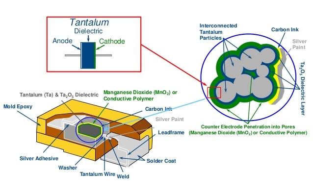
Tantalum/NbO capacitor high CV strategy is to create a very high surface area created by porous ultra fine tantalum powder sintered slug in combination with a very but stable dielectric – oxide of tantalum(Ta2O5)/niobium (Nb2O5). This structure is electrically connected by MnO2 (conventional) or conductive polymer second electrode. The use of stable dielectric is bringing stability of electrical parameter with voltage, temperature and life time. The porous structure, on the other hand, can not offer such low ESR values as MLCC technology.

Tantalum manufacturing process can be viewed in a video for example [5].
The historical issue with tantalum capacitors was a local overheating in high current surge conditions with ignition risk failure mode. Thus a 50% derating (use of capacitor at half rated voltage) was recommended in high surge applications such as a DC/DC converter input side or at direct connection to battery. This issue was particularly addressed by conductive polymer electrode that reduces the ignition failure mode and lower the ESR. Conductive polymer on the other hand is more sensitive for high humid and high temperature parametric shift, thus for certain applications such automotive, dedicated humidity more robust series shall be used.
NbO capacitors with MnO2 electrode are having similar characteristics to tantalum MnO2 capacitors, while offering additional safety function and longer-term reliability are reported. The capacitor technology is however limited to maximum 10V rated capacitors. [6].
Tantalum raw material availability and conflict free tantalum ore source were other topics considered as an issue for tantalum capacitors. The tantalum supply issues was raised during a bubble demand in 2000, when mines could not double the production in couple of month … the market came to more balance with years and for this article considering tantalum replacement to MLCC as alternative it is irrelevant. Tantalum capacitors leading manufacturers such as AVX or Kemet have established (together with other international institutions and government) certified system of tantalum ore mining and processing in Congo out of conflict areas with target to support a local infrastructure and people lives in Africa. Conflict-free declarations are available from manufacturers upon request.
5. Main Performance Comparison
5.1. Capacitance vs Temperature

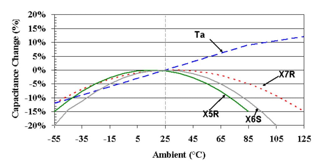
Changes in frequency, temperature, time, or voltage have significant effects on the performance characteristics of MLCC Class II capacitors. Some of the characteristics that are significantly affected by these changes include capacitance, DF, and insulation resistance. The most commonly used “stable” MLCC class II dielectric materials are X5R(85degC) and X7R(125deg.C) with allowable shift of capacitance +/- 15% at the entire operating temperature range. The MLCC capacitance value may decrease towards lower and higher temperatures, while tantalum capacitance is more linear from lower capacitance at lower temperature to capacitance increase at higher temperatures – as illustrated in Fig.3. below. More details can be followed at [7] and [8].
5.2. Capacitance vs Voltage
The effective capacitance value of a MLCC capacitor changes according to the direct current (DC) or alternating current (AC) voltage due to its ferroelectric dielectric type nature. Tantalum capacitors have much stable capacitance with voltage performance. This is bringing difficulties for MLCC in replacement of tantalum capacitors, as its effective capacitance may be significantly lower compare to the rated specification value in real applications. In opposite replacement, tantalum may provide even better capacitance stability replacing MLCCs.


More details on capacitors versus voltage behaviour can be found in [9].
When using MLCC capacitors in electronic equipment used for applications such as ripple rejection in power lines, the design must take into account the operating voltage conditions. However, the actual capacitance voltage drop may be manufacturer/product type specific as the actual MLCC component behavior is impacted by a number of design parameters such as dielectric grain size, thickness of dielectric or firing temperature. This makes MLCC to MLCC vendor replacement even more difficult with a risk to an operational range of the end electronic device. Such risk is not present when replacing MLCCs by tantalum capacitors with stable capacitance value.
5.3. Capacitance, IMP and ESR vs frequency
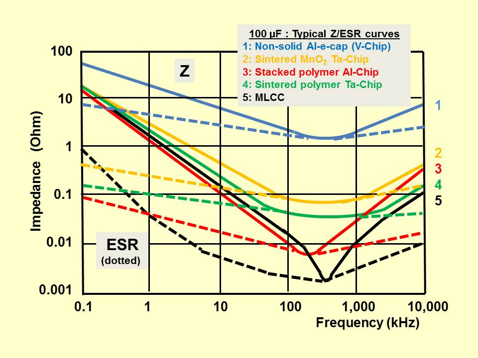
The Capacitance, Impedance and ESR versus frequency behavior differences between MLCC and tantalum capacitors are impacted by the two main technological differences:
- MLCC capacitors are electrostatic multilayer structure capacitors with very low internal electrodes resistance and high design flexibility that enables low self-inductance electrode layout. Thus capacitance is flat with frequency up to its resonance point. Tantalum/NbO capacitors are belonging to electrolytic capacitors, where connection to the second electrode high surface is provided by an electrolyte (MnO2 or conductive polymer) that add additional internal resistance and causing some capacitance drop with frequency close to its resonance frequency. Conductive polymer parts with lower ESR are exhibiting only a minor capacitance decrease, while this effect is in place of higher ESR MnO2 solid electrolyte.
- Multilayer MLCC structure is ideal to suppress ESR at higher frequencies > 100kHz that makes MLCC capacitors lowest ESR and high ripple current capable solution for number of DC/DC converter applications. Nevertheless, the MLCC high K material is linked with high dielectric losses at low frequencies. Thus ESR of MLCC below about 1kHz may be higher compare to tantalum/NbO capacitors. This is resulting in superior smoothing functionality of tantalum capacitors compare to MLCC at low frequencies. This is not commonly known and obvious characteristics as specification datasheet is referring ESR values at high frequencies only (100kHz).

Practical application notes:
- MnO2 tantalum capacitors may have a lower ESR and better filtering capability to smooth 216Hz signal (telecom applications) than MLCC capacitor.
- MLCC capacitors are showing significantly lower ESR at higher frequencies that fits with high power supplies needs
- Very low ESR of MLCC capacitors is not always the advantage. Such low ESR is posing more strict requirements on IC converters feedback loop quality. Improper use may result in oscillations and instability. (especially important for LDO) see also [14]
5.4. Ripple Ratings
The ripple current capability of a capacitor is one of the key parameters to consider when selecting a capacitor for a given application. The AC ripple current causes power dissipation and heating in capacitors. In most capacitors, temperature rise is a function of ripple current and equivalent series resistance. The maximum power dissipation and continuous ripple current load shall not exceed the capacitor specified values.
MLCC capacitors are providing very low ESRs with small power dissipation and withstand high ripple currents. Careful evaluation of power load profile and continuous ripple load characteristics are necessary when replacing MLCC by tantalum capacitors in power supply circuits. Tantalum capacitors with conductive polymer are featuring lower ESR values and thus it may be more suitable alternative for higher power circuits.
The ripple load needs to be also examined in the entire operating temperature range. Ceramic capacitors at higher temperatures have less ripple current capability compared to those operating at lower temperatures. This is not the case of tantalum/NbO capacitors with MnO2 electrolyte as ESR is decreasing with temperature. Conductive polymer has about a neutral ESR temp coefficient, thus its ripple characteristics does not change with temperature within its operation range.
some more notes about capacitor ripple currents can be found in [10].
Smoothing capacitor calculations in more detail description can be followed for example on website [11]. Important note for correct benchmarking between the MLCC and tantalum capacitors is to reflect the MLCC capacitance drop with DC/AC voltage and temperature as mentioned above, and effective capacitance value has to be used (can be 20-80% of rated capacitance value depending on the voltage derating level use).
6. CONCLUSION – Suitable Replacement Applications
Based on the above discussion and performance comparison we can assume the suitable applications for tantalum to MLCC replacement:
A. LOW RISK:
– all applications, where very low ESR and high ripple current load is not a prime requirement, such as circuit functions – coupling/decoupling including audio circuits, selected filtering, timing etc.
Checklist:
- a) low ESR requirements and high ripple current load Yes/No/Level
- b) DCL leakage level in case of battery operated circuit
Tantalum or NbO capacitors in these applications are representing even more stable, reliable solution that may be even superior compare to the original MLCC capacitor.
related blog on coupling applications, see reference [12].
B. MORE DETAILED EVALUATION NEEDED:
– smoothing applications typically at DC/DC converters with high power load requirements.
Checklist:
- a) smoothing frequency required ! not a general specification table parameter ! – at low frequencies ESR of MLCC capacitors may be even higher than tantalum. Use of tantalum capacitors is thus possible with even improved performance.
- b) beware of the required low ESR and ripple load specification values as the critical characteristics as the low ESR may be the main limiting factor for the circuit operation.
- c) return to b) and check the low ESR / ripple load requirements in the entire end device operating temperature range
- d) consider appropriate derating rules for tantalum, NbO and polymer capacitors. Follow manufacturers recommendations – for example by Kemet [18], AVX [19], Vishay [20]
related technical papers on capacitors selection for DC/DC converters can be found in [13] and detailed technical paper from AVX on DC/DC capacitor benchmarking [14].
The Final Word
Situation on the market is rather dynamic, thus it can not be guaranteed that tantalum or NbO capacitor alternatives will be available with shorter leadtime than MLCC, nevertheless the main purpose of these guidelines is to provide a basic info on possible replacement considerations to be flexible with some more choices on mind to avoid line stops.
References
[1] D.Zogbi, Paumanok, TTI Market Eye, March 2018: “MLCC shortages are creating challenges in multiple end markets in 2018” link here
[2] D.Zogbi, Paumanok, TTI Market Eye, February 2018: “An Update on Installed Global Capacitance in 2018” link here
[3] D.Zogbi, Paumanok, TTI Market Eye, June 2017: “MLCC Shortages and Why They Might Last Longer than Expected”, link here
[4] Murata Capacitor Room: “Basics of capacitors – How multilayer ceramic capacitors are made”. link here
[5] AVX tantalum manufacturing video. link here.
[6] AVX technical paper, 2005 ” New Tantalum Technologies Tantalum Polymer and Niobium Oxide Capacitors”, link here
[7] Kemet Technical Library, 2008:”Comparison of Ceramic and Tantalum Capacitors”, link here
[8] Capacitor Faks Blog: “Class II ceramic dielectrics: types, performance and applications”, link here
[9] Murata Capacitor Room: “The voltage characteristics of electrostatic capacitance”, link here
[10] Capacitor Faks Blog: “Ripple Current and its Effects on the Performance of Capacitors”, link here
[11] Ian Poole, Radio Electronics website: “Capacitor Smoothing Circuits & Calculations”, link here
[12] Capacitor Faks Blog: “Capacitor Selection for Coupling and Decoupling Applications”, link here
[13] EPCI e-passive book: “Capacitors in DC/DC converters”, link here
[14] AVX Technical paper: “DC/DC Converter Output Capacitor Benchmark”, link here
[15] DigiTime news:”MLCC prices to rise 40-50% in 2Q18″, link here
[16] D.Zogbi, Paumanok, :”Paumanok note on Tantalum Capacitors lead times continued to stretch”, link here
[17] D.Zogbi, Paumanok,Linked In note:”MLCC Supply Remains Tight”, link here
[18] Kemet Technical Library,”Derating Guidelines for Surface Mount Tantalum”, link here
[19] AVX Technical paper:”Voltage Derating Rules for Solid Tantalum and Niobium Capacitors”, link here
[20] Vishay Frequently Asked Questions:” Why are voltage and temperature derating needed for tantalum capacitors?”, link here
![]()
This article and featured image can be shared under a Creative Commons Attribution-ShareAlike 4.0 International License


