


This article based on Monolithic Power Systems article explains what is an LLC resonant converter, its basic principles and characteristics.
Key Takeaways
- The LLC Resonant Converter efficiently converts DC to DC using a resonant tank circuit, achieving zero-voltage and zero-current switching.
- Designers can choose between full-bridge and half-bridge topologies for power switches based on application needs.
- LLC converters excel in high-power applications due to their efficiency and reduced component count.
- Soft switching significantly minimizes losses and improves efficiency during operation under varying loads.
- AI design tools facilitate quicker iterations in LLC Converter design, enhancing learning and optimizing performance.
Introduction
LLC resonant converter is a type of DC-to-DC power converter that is widely used in electronic applications for efficient power conversion. It uses a resonant tank circuit composed of an inductor (L) and two capacitors (C) to convert an input voltage to a different output voltage.
The resonant operation allows for zero-voltage switching (ZVS) or zero-current switching (ZCS), reducing switching losses and improving efficiency, especially under varying load conditions.
LLC resonant converters have gained significant attention in power electronics due to their ability to meet the demanding performance requirements of modern power supply designs. Among the diverse family of resonant converter topologies, LLC stands out as one of the most prominent.
Resonant tanks, the foundation of LLC converters, are circuits composed of inductors and capacitors that oscillate at a specific frequency known as the resonant frequency. This unique characteristic of resonant tanks enables LLC converters to achieve higher switching frequencies (fSW) and minimize switching losses.
In high-power, high-efficiency applications, switch-mode DC/DC power converters with LLC resonant converters are particularly advantageous. They are ideal for power supply systems with delicate components (e.g., high-end consumer electronics) or power-demanding operations (e.g., charging electric vehicles).
At the extreme end of this power and frequency range, LLC resonant conversion is also emerging inside next-generation AI data center racks. NVIDIA’s announced 800 V DC “AI factory” architecture uses an LLC resonant stage for the 800 V → 48 V rack bus step-down:
| Power Stage | Key Passive Components | Critical Parameters |
|---|---|---|
| 800 V → 48 V resonant converter | High-frequency resonant capacitors (500 V–1 kV); LLC resonant inductor/transformer; output filter capacitors (50–100 V) | Low loss at 500 kHz–2 MHz; high Q; accurate inductance tolerance |
Source: AI Hardware Passive Components Dossier, Passive Components Blog.
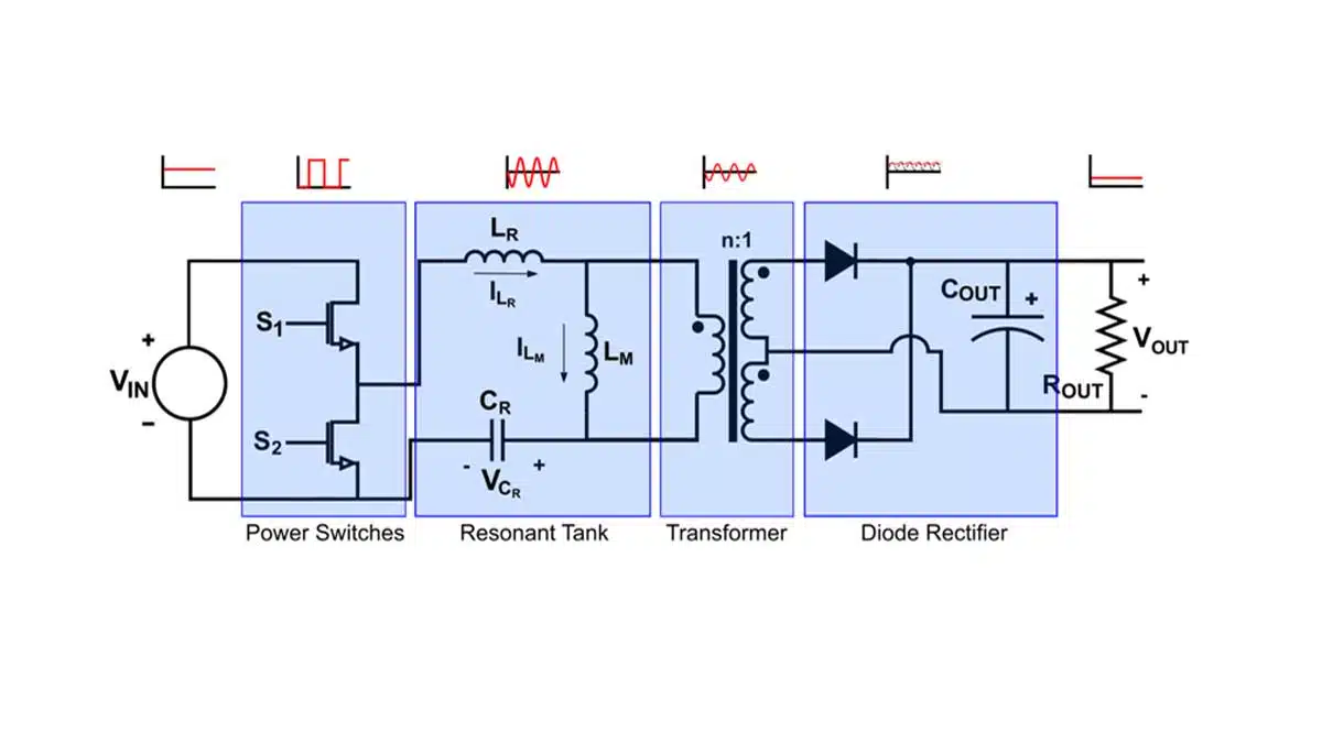
An LLC converter comprises four essential blocks: power switches, resonant tank, transformer, and diode rectifier (as depicted in Figure 1). The process begins with the MOSFET power switches converting the input DC voltage into a high-frequency square wave. This square wave then enters the resonant tank, where it undergoes a process of harmonic elimination, resulting in the generation of a sine wave with the fundamental frequency.
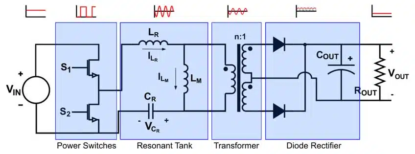
The sine wave is subsequently transmitted to the secondary side of the converter through a high-frequency transformer. This transformer plays a crucial role in scaling the voltage, ensuring that it meets the specific requirements of the application. Finally, the diode rectifier converts the sine wave into a stable DC output.
The remarkable ability of LLC converters to maintain high efficiency even at extremely high power levels stems from their resonant nature. This resonant characteristic enables soft switching in both the primary and secondary sides of the converter, leading to increased efficiency by reducing switching losses.
In addition to saving board space, an LLC topology eliminates the need for an output inductor, allowing all inductors to be integrated into a single magnetic structure, reducing area and cost. This integration also enhances electromagnetic compatibility by simplifying and reducing the cost of shielding a single structure compared to three.
Power Switches
Power switches can be implemented in full-bridge or half-bridge topologies, each resulting in a unique output waveform (Figure 2).
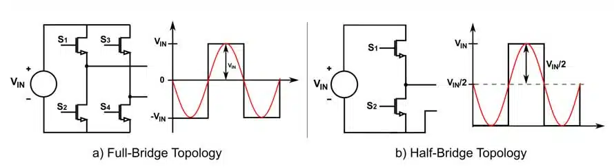
The primary distinction between these topologies lies in the generation of the output waveform. Full-bridge topologies produce a square wave with no DC offset and an amplitude equal to the input voltage (VIN). Conversely, half-bridge topologies generate a square wave with a DC offset of (VIN / 2), resulting in a half the amplitude of the full bridge wave.
Each topology presents its own set of advantages and disadvantages. Full-bridge topologies require more transistors, making their implementation more expensive. Additionally, the increased number of transistors introduces higher series resistance (RDS(ON)), potentially leading to increased conduction loss. On the other hand, a full-bridge implementation reduces the necessary transformer turn ratio (N) by half, thereby minimizing copper loss in the transformer.
In contrast, a half-bridge topology is more cost-effective to implement and offers the benefit of reducing the RMS current across the capacitor by approximately 15%. However, it also introduces higher switching loss.
Considering these trade-offs, it is recommended to use a half-bridge power switch topology for applications with power below 1kW, while a full-bridge topology is preferred for applications requiring higher power.
Resonant Tank
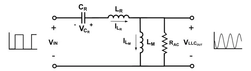
The resonant tank, composed of a resonant capacitor (CR) and two inductors—the resonant inductor (LR) in series with the capacitor and transformer, and the magnetizing inductor (LM) in parallel—filters out the square wave’s harmonics, outputting a sine wave of the fundamental switching frequency to the transformer’s input.
The resonant tank’s gain varies with frequency and load applied to the secondary side (Figure 4). Designers must tune these parameters to ensure the converter’s efficient operation across a wide range of loads by designing the tank’s gain to exceed 1 for all load values.
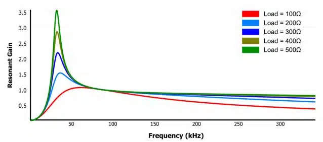
The LLC converter’s wide operation range and high efficiency stem from the resonant tank’s dual inductors. Let’s examine how this works by considering the tank’s response to heavy and light loads, depending on the inductor.
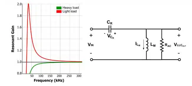
Figure 5 illustrates the resonant tank’s gain for various loads if it were solely composed of the resonant capacitor and the magnetizing inductor. At light loads, a distinct peak in the resonant tank’s gain is evident. However, the gain for heavy loads doesn’t peak—instead, it exhibits a dampened response and only achieves unity gain at extremely high frequencies.
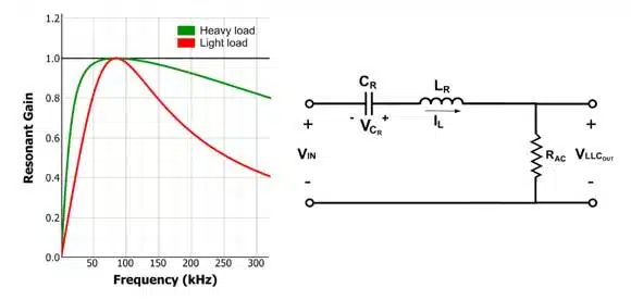
If the resonant tank were solely composed of the resonant inductor (LR) in series with the resonant capacitor, the behavior would differ. The gain doesn’t exceed 1, but when the load is heaviest, the tank achieves unity gain much faster compared to the parallel inductor.
By implementing both inductors in the resonant tank, the resulting frequency gain response ensures that the converter can adequately respond to a much larger range of loads — in addition, it can enable stable control for the entire load range (see Figure 4). The resulting LLC tank has two resonant frequencies (fR and fM), calculated with Equation (1) and Equation (2), respectively.
The tank’s gain response is dependent on three parameters: the load, normalised inductor, and normalised frequency.
The load is expressed through the quality factor (Q), which is dependent on the load connected to the output. However, using the value of the load is not accurate, since there is a transformer and a rectifier between the output of the resonant tank and the load (see Figure 1). Therefore, we must use a primary-referenced value for the load, called RAC. RAC and Q can be estimated with Equation (3) and Equation (4), respectively:
The normalized frequency (fN) is the ratio between the MOSFET’s switching frequency (fSW) and the tank’s resonant frequency (fR). It can be calculated using Equation (5):
The normalized inductance (LN) is expressed as the relationship between the resonant and magnetizing inductors, estimated using Equation (6):
With these parameters, we can calculate the converter’s gain response using Equation (7):
Note that these calculations are based on first harmonic analysis (FHA). This approach is suitable because we assume that the LLC operates within the resonant frequency (fR). By applying Fourier analysis, we can represent the resonant tank’s input as a square wave composed of multiple sine waves with varying amplitudes and frequencies. Since the resonant tank filters out all sine waves with frequencies different from the fundamental fSW, we can disregard all waves except the fundamental sine wave, significantly simplifying our analysis.
Soft Switching
A notable feature of LLC converters is their ability to perform soft switching.
Soft switching aims to minimize switching losses by synchronizing the electronic switches with the natural rise and fall of current and voltage within the circuit. This ensures that the switches turn on and off at the most optimal points. If switching occurs when the current is close to zero, it’s known as zero-current switching (ZCS). If switching happens at low voltages, it’s called zero-voltage switching (ZVS). LLC converters possess the capability to perform both ZVS and ZCS due to their resonant nature.
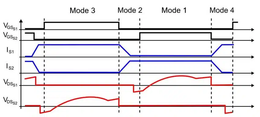
Figure 7 illustrates the four fundamental operating modes of an LLC converter. Modes 1 and 3 represent the conventional LLC operation, which we’ve already discussed. In Mode 1, the current flows from the source to the resonant tank and the secondary of the transformer (Q1 is on, while Q2 is off). Conversely, in Mode 3, the remaining stored power in the resonant tank is transferred to the secondary of the transformer with the current flowing in the opposite direction compared to Mode 1 (Q1 is off, and Q2 is on). ZVS occurs during Modes 2 and 4, when both switches are turned off. During these periods, current passes through the body diode of the transistor (e.g., Q2 in Mode 2 or Q1 in Mode 4), which is also known as freewheeling.
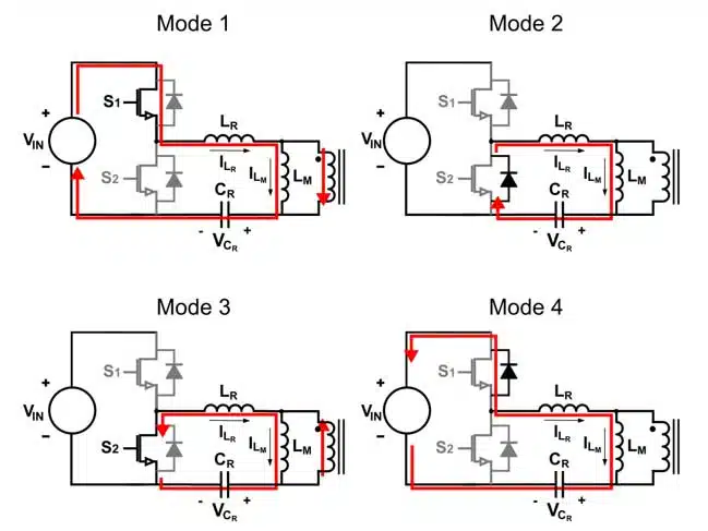
Freewheeling results in a drop in the voltage across the transistor (VDS) until it approaches zero, limited by the minimal voltage drop of the body diode. Since this happens when both gate signals are low, by the time the circuit transitions from Mode 2 to Mode 3 or Mode 4 to Mode 1, the voltage across the transistor is close to zero, thereby minimizing switching losses.
LLC Resonant Converter: Practical Design Insights & AI Modern Tools
Key Design Challenges
- Frequency Trade-off: Higher frequency means smaller magnetics and greater power density, but more losses. Lower frequency improves efficiency and thermal management but increases size and cost. I learned (the hard way) to be conservative after an overheated transformer in a previous phase-shift full-bridge design.
- Resonant Frequency Accuracy: Academic methods (time-domain versus frequency-domain) can lead to over-engineering; in reality, closed-loop control sorts out many fine details. I spent too much time on theoretical gain curves when practical confidence matters more.
- Integrated Inductor Challenge: Integrating the resonant inductor within the transformer can save space and improve coupling, but balancing leakage and magnetizing inductance is highly sensitive to winding geometry. Spreadsheet modeling helped, but real feedback only comes from prototype testing.
- Planar vs Conventional Magnetics: Planar transformers appeal for thermal efficiency and size, but parasitics and noise problems can undermine expectations. Without rapid simulation and modeling, experimenting with geometry is risky and resource-intensive.
- Time Pressure: Delivering a working design quickly—without perfection—forced me to rethink the value of simulation and fast iteration.
To see how these resonant-tank parameters play out in a real design, consider a 3 kW single-phase AC/DC front end for a server or telecom supply (PFC stage followed by an LLC stage producing a 400 V DC bus):
| Design Parameter | Example 3 kW LLC Front End |
|---|---|
| Mission profile | 90–265 V AC input, 70–100% load, 40 °C ambient, 10-year target life |
| DC-link capacitors | 450 V metallized polypropylene, operated at ~380 V DC (≈85% of rating) |
| Resonant capacitor (Cr) | Polypropylene film or C0G/NP0 MLCC, sized for 100–150 kHz switching |
| Transformer | Ferrite core; leakage/magnetizing inductance set to meet LLC control targets |
| EMI filter | Common-mode chokes, differential inductors, X/Y capacitors matched to the target insertion-loss curve |
Source: Passive Components for Power Converters Dossier, Passive Components Blog.
Why AI Design Tools Matter
The interdependence and sensitivity of the LLC topology make it perfect for AI-based design tools. Traditionally, weeks of simulation, prototyping, and waiting for results hamper learning. Modern platforms like collapse entire feedback loops into seconds. You define requirements, explore the design space, compare magnetics (planar vs conventional) in real time, and can quickly iterate and export simulation models for further testing in LTSpice.
Design Workflow (with AI Assistance)
- Define Power Requirements: Input/output voltages, load range.
- Select Switch Topology: Half-bridge for <1kW, full-bridge for higher power.
- Design Resonant Tank: Optimize LR, LM, CR for target resonance.
- Tune Parameters for Efficiency: Simulate and adjust for normalized frequency, inductance ratio, and quality factor.
- Implement Soft Switching: Ensure ZVS/ZCS operation under varying loads.
- Validate and Optimize: Prototype and test; iterate parameters with AI to quickly reach workable solutions.
Lessons & Best Practices
- Start with a reliable modeling platform—AI tools speed up learning and avoid wasted cycles
- Don’t over-prioritize theoretical accuracy where control systems can compensate
- Value rapid prototyping—chasing the “sweet spot” in LLC design is iterative
- AI does not replace engineering intuition, it multiplies its effect by providing instant feedback
- Share experiences (even failures): Real learning comes from the test bench, not just datasheets
With modern AI design platforms, engineers can focus on insight rather than on iteration. The right tools collapse lengthy design cycles and allow immediate exploration—making it possible to keep asking “what if?” rather than “what now?”.
Conclusion
In conclusion, comprehending how an LLC resonant tank functions is essential for designing an LLC converter. The tank’s resonant characteristics make the LLC converter highly sought after, as it can maintain efficient and stable operation across a wide range of loads and power levels. However, this resonance also necessitates meticulous attention to circuit parameter design, as the tank’s gain response is influenced by various factors, including the load and the converter’s operating point (refer to Equation (7)).
Further reference case study:
- Designing a 2 kW LLC Transformer with Integrated Resonant Inductor
- LLC Transformer Design and Simulation
Read also the related articles in this series:
For a full walkthrough of how these resonant-tank parameters translate into component selection — DC-link capacitor derating, resonant capacitor technology, transformer design and EMI filter sizing — for a real 3 kW server/telecom LLC front end, see our Passive Components for Power Converters Dossier.
For how this same resonant tank scales up to the 800 V → 48 V bus stage inside next-generation AI data center racks, see our AI Hardware Passive Components Dossier.
- Selection of Capacitors for DC/DC Converters
- Selection of Storage Inductors for DC/DC Converters
- Input filters for DC/DC converters
- Switching vs Linear Power Converters Compared
- Buck Converter Design and Calculation
- SEPIC Converter Design and Calculation
- Boost Converter Design and Calculation
- Fly-Buck Converter Explained and Comparison to Flyback
- Flyback Converter Design and Calculation
Frequently Asked Questions about LLC Resonant Converters
An LLC resonant converter is a DC‑DC power converter that uses a resonant tank circuit (inductor and two capacitors) to achieve efficient voltage conversion. It enables zero‑voltage or zero‑current switching, reducing losses and improving efficiency across varying loads.
The LLC topology is widely used because it maintains high efficiency at high power levels, eliminates the need for a separate output inductor, reduces board space, and improves electromagnetic compatibility. It is ideal for applications such as consumer electronics and electric vehicle charging.
The converter consists of four essential blocks: MOSFET power switches, a resonant tank (inductor and capacitor network), a high‑frequency transformer, and a diode rectifier. Together, they convert DC input into a stable DC output with minimized switching losses.
Soft switching synchronizes transistor switching with natural current and voltage waveforms. This allows zero‑voltage switching (ZVS) or zero‑current switching (ZCS), significantly reducing switching losses and improving efficiency.
How to Design an LLC Resonant Converter
- Define Power Requirements
Determine the input voltage, desired output voltage, and load range. This sets the foundation for selecting the resonant tank parameters.
- Select Power Switch Topology
Choose between half‑bridge (recommended for <1kW applications) or full‑bridge (for higher power). Consider trade‑offs in cost, conduction losses, and transformer design.
- Design the Resonant Tank
Choose between half‑bridge (recommended for <1kW applications) or full‑bridge (for higher power). Consider trade‑offs in cost, conduction losses, and transformer design.
- Tune Parameters for Efficiency
Use normalized frequency (fN), inductance ratio (LN), and quality factor (Q) to optimize gain response. Ensure the tank gain exceeds 1 across all load conditions.
- Implement Soft Switching
Design for zero‑voltage and zero‑current switching to minimize switching losses. Verify operation modes to ensure efficiency under varying loads.
- Validate and Optimize
Simulate and test the converter under different load conditions. Adjust tank parameters and transformer ratios to achieve stable, efficient performance.


