This application blog article by Benno Kirschenhofer, Panasonic Industry Europe discusses passive components selection guide for solar inverters including capacitors, resistors and inductors.
Introduction
As the world moves towards making more eco-friendly responsible choices, the demand for sustainable and renewable energy has driven consistently high growth in the solar inverter market.
A solar inverter (also called a photovoltaic or PV inverter) converts direct current (DC) into alternating current (AC) and is widely used in solar photovoltaic power generation systems.
Solar inverters available today are generally divided into three types: central inverters, string inverters and micro-inverters.
- Central inverters are mainly used in large-scale ground power stations, suitable for high-voltage grid connections. The power range is normally between 100kW and 2500kW.
- String inverters, also known as distributed inverters, are mainly used in industrial, commercial and residential areas. Power stations that use string inverters are not generally very large, and they are integrated into the national supply through full or surplus power grid connection. The power range is normally up to 200kW. String inverters are most commonly used and encountered in our daily lives.
- Micro inverters are mainly used for direct integration on battery boards that are suitable for small household power stations.
In this blog article, we would like to introduce Panasonic’s passive components and show how they can contribute to optimizing the design of string inverters.
CAPACITORS FOR SOLAR INVERTERS
Standard Film Capacitors
Regardless of the type of solar inverter, the key requirements are high efficiency, high reliability and input voltage with a wide range of capacitance values.
This contribution of attributes is exactly why Panasonic’s various metallized PP film capacitors can play an essential role in a solar inverter’s circuit design as they feature a large current handling ability, high reliability and proven safety performance. Our capacitors are used for input & output filtering, EMI suppression, snubber and DC link circuits.
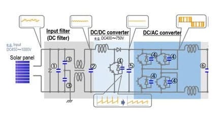
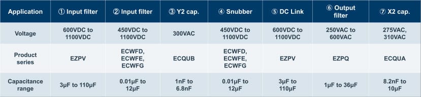
On the input side of the primary DC filter circuit ① as well as for the DC-link circuit ⑤, DC-rated EZPV series film capacitors provide DC filtering. Parts with voltage ratings of up to 1300VDC and a wide capacitance range of up to 110μF are available as one single component; both 2-pin and 4-pin terminal solutions are available.
On the input side of the DC/DC converter circuit, as well as in snubber circuits (② + ④in Figure 1), DC-rated ECWFD series (coating type), ECWFE and ECWFG (box type) film capacitors, are ideal solutions for smoothing. Various rated voltage values are available from 450VDC up to 1100VDC.
The capacitance range stretches from 0.01μF up to 12μF. Excellent safety performance (thanks to a built-in fuse function – see Figure 2.), high-frequency characteristics and high ripple current capacity help these three film capacitor series devices to optimize the high voltage circuit of a solar inverter. AC-rated EZPQ series film capacitors with a higher rated voltage range of 250VAC to 600VAC are also available. This industrial-grade AC capacitor can be used as an output filter.
Considering that reliability – especially in humid conditions – is critical for solar inverters which are used outdoors, Panasonic has developed its own enclosure sealing technology and 100% aluminium vapour deposition processes which enable our film capacitors to achieve high humidity resistance – see Figure 3..
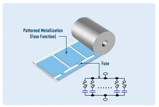

Figure 4. below, shows the key attributes of Panasonic’s film capacitors when used in solar inverters:
We are committed to high output, high safety and high reliability, so Panasonic’s film capacitors can help optimize your solar inverter design.
OS-CON (Polymer Aluminum Capacitors)
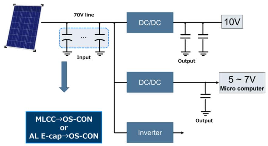
Panasonic OS-CON conductive polymer solid aluminium capacitors play a major role in the optimization of solar inverters. To efficiently generate energy from the sun, the solar panel must absorb energy from the sun continuously as the earth rotates. By detecting and tracking the live position of the sun and adjusting the angles of the panel to ensure that it always faces the sun the solar energy harvest can be maximized.
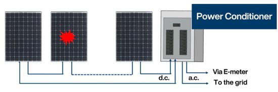
Conventional solar inverters have a centralized power conditioner that controls the entire module.
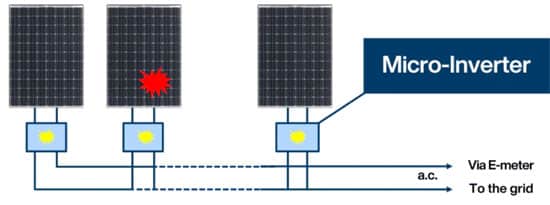
New requirements that these micro-inverters demand include a long lifetime of 5-10 years, space-saving, and cost-reduction. OS-CON capacitors satisfy these new requirements.
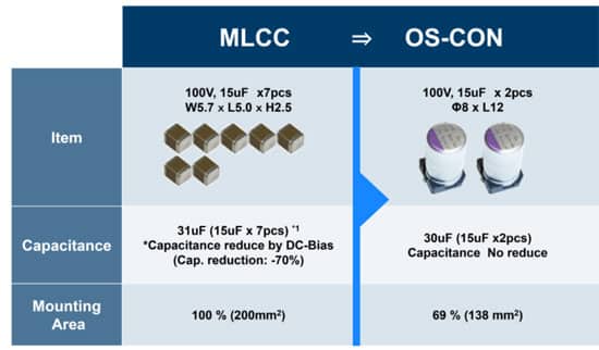
A single OS-CON can replace seven MLCCs in a micro-inverter design, reducing PCB space by 31% – see Figure 8. Another benefit of using OS-CON is that capacitance is not reduced, unlike MLCCs which cause a reduction of capacitance due to DC-Bias.
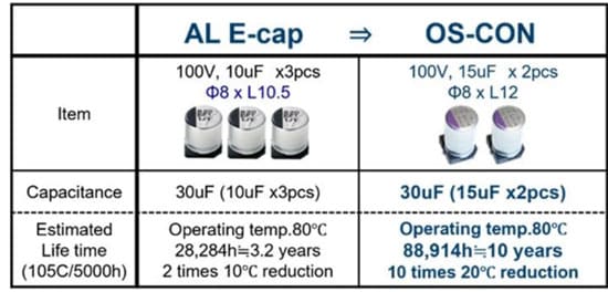
Aluminium electrolytic (lytic) capacitors can also can be replaced by OS-CON capacitors, increasing the life of the micro-inverter. Using OS-CON capacitors in this example also saves space, since two OS-CONs can replace three electrolytics – see Figure 9.
RESISTORS FOR SOLAR INVERTERS
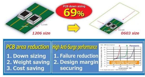
Many resistors are used in a solar inverter circuit- see Figure 10. Current requirements focus on high voltage, high efficiency for energy saving, and long lifetime. For the resistor, this means high reliability with long lifetime, high voltage-withstand capability and high accuracy. Panasonic has a variety of resistor families that can be employed in solar inverters applications.
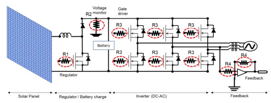
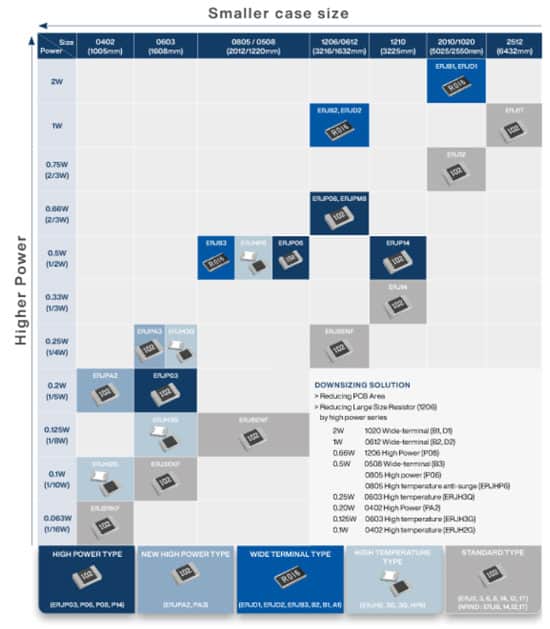
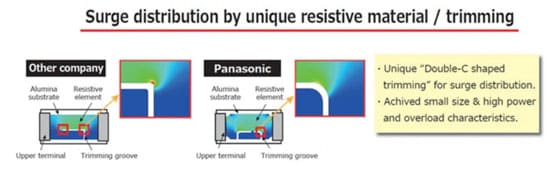
For the regulator and voltage-sense, ERJP series resistors can be used thanks to their high power load specifications and superior anti-surge and anti-pulse-withstand performance compared to standard metal film resistors. Thanks to Panasonic’s unique resistive element trimming shape, it is possible to achieve higher power in smaller chip size and improved overload characteristics.
Gate driver resistors are normally required to have a high power capacity and to be able to survive the high temperatures caused by heat generated within the IGBT and inverter.
ERJH series resistors can achieve high heat resistance when exposed to a harsh thermal environment, reaching maximum operating temperatures of 175℃ and rated operating temperature of 105℃. Additionally, improved thermal shock resistance is achieved thanks to high-heat-resistant materials and soft electrode materials, thereby reducing the risk of solder cracks.
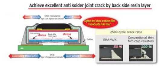
In the motor drive control unit, resistors are required for amplifier and feedback circuits. Key requirements are high reliability, long life and stable resistance values. Panasonic’s thin film resistor ERA*A series (High-reliability type) and ERA*V/K series (High stability and reliability type) can contribute to obtain high accuracy.
ERA*V/K resistors reduce solder joint cracking by adding a resin layer on the underside and allow to achieve high precision and a longer life than current devices thanks to improvements in the construction and material. Also, ERA*V/K series structure guarantee sulfuration resistance.
These improvements make them suitable for the harsh operating conditions that micro-inverter applications routinely encounter.
INDUCTORS (POWER CHOKE COILS)
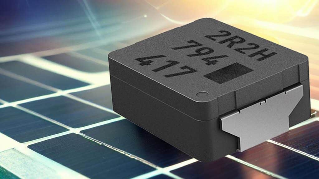
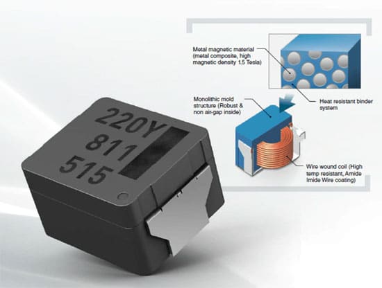
Solar inverters need inductors that are capable of handling high voltages and large currents in the main circuit. Panasonic inductors, thanks to their high-quality design, can meet these requirements ensuring a stable inductance value during lifetime. In addition to the inductor’s role in the primary circuit, power inductors are also used in the auxiliary circuit for the controller and gate drivers, where digital logic provides critical controlling and monitoring functions for solar energy harvesting systems. Since high switching speeds are employed and operating conditions can be harsh, high-performance power inductors such as the Panasonic Metal Composite ETQP family are required.
As a pioneer of metal composite power inductors, Panasonic offers a broad line-up of power inductors that offer the highest efficiency and reliability.

High efficiency
One of the most important requirements of a power inductor for a DC/DC converter is high power efficiency. Inverter suppliers are facing tough demands for reduced inverter system size and higher efficiency. So the challenge for the inductor supplier is to provide an inductor at a small size with high current capability and minimal heat dissipation.
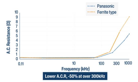
The Panasonic ETQP high-performance inductor series (ETQP*M***Y**) exactly fulfils this requirement with a broad line-up that covers sizes from 5x5mm to 10x10mm, supporting currents of up to 39.7A with an inductance range of 0.33 – 100µH. The high efficiency is a result of both low AC resistance and low DC resistance, enabled by the use of a unique magnetic material with high permeability, as well as a unique wire winding structure. As a result, ETQP*M***Y** inductors support a higher total system efficiency see Figure 17..
A general trend in the electronic industry is the standardization and modulization of systems. However, this means that passive components suppliers need to provide products which scale over a broad range of requirements in regard to electrical power capability. The high current capability of parts such as the ETQP series (ETQP*M***Y**) greatly supports the standardization of solar inverter systems, as they support a wider range of current flow, depending on the requirement of the individual system.
High-temperature stability
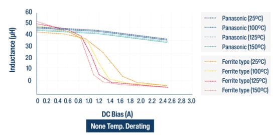
Panasonic metal composite power choke coils not only exhibit stable inductance over current but are also stable with temperature, as you can see in the graphon Figure 18. This is in stark contrast to ferrite inductors, where the inductance value is influenced by the temperature of the inductor, requiring great effort from design engineers to qualify the component for different temperature ranges when used in solar inverters. With stable temperature behaviour, much less time is required for qualification, which reduces development costs and time.
GATE DRIVER
Long life stability
Another area within a solar power inverter that requires a power inductor is the gate driver of the FET that transforms the DC current of the battery to the 3-phase sine wave, which is fed into the power grid. The biggest advantage of the Panasonic metal composite power inductor is the stability of its inductance value over its lifetime. While the inductance of a ferrite inductor will vary with age, the metal composite material is free from any effects of ageing, helping the inverter manufacturer to guarantee a system that functions over its entire specified lifetime. Panasonic specifically recommends the ETQP LP series (ETQP*M***KV*) as the most cost-efficient metal composite inductor solution for the gate driver of an inverter.
High-temperature stability
As is the case with the DC/DC converter, the power inductor of the gate driver circuit also greatly benefits from a stable temperature behaviour of the inductance value. This attribute also helps to reduce the development and qualification time of the gate driver circuit, as engineers do not need to consider a fluctuation of the inductance value of the inductor, which is not only influenced by the power loss of the inductor itself but also by the heat dissipated by surrounding components.
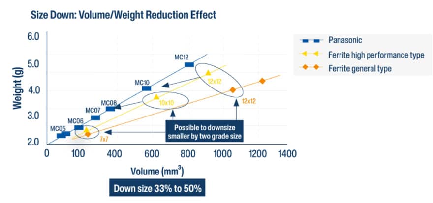
Miniaturization
As already stated, designers of inverter systems are under constant pressure to make their systems smaller and more efficient. Compared to ferrite inductors, metal composite inductors have a much higher energy density, which leads to a size reduction of 30% – 50% for comparable current specifications. So a designer can save PCB space or run at higher currents simply by using Panasonic’s metal composite inductors rather than traditional ferrites.