


source: EDN article
Steve Taranovich -September 08, 2016
The ongoing challenge of multiband/multistandard RF solutions for smartphones requires the addition of more bands into the same or smaller physical space in the handset. In addition, performance must improve in the next generation of smart phones.
In long-term evolution (LTE) carrier aggregation (CA) and beyond, the need for multiple bands operating simultaneously through one antenna necessitates so many added challenges for filters and duplexers. Isolation loss and linearity are probably the most difficult to achieve.Reconfigurable radios are also another path which can be investigated going forward. With the radio spectrum becoming more crowded, smart cognitive radios are being looked at. The problem is that mobile phone manufacturers do not like having to add new models to keep up with bandwidth needs. This is not very cost effective.
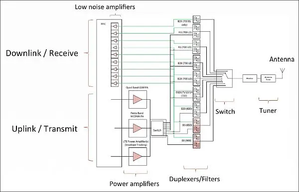
The coming carrier aggregation and Multiple-In-Multiple-Out (MIMO) designs will be needed to meet the needs of both interim LTE-Advanced and the ultimate arrival of 5G. Smaller and lower cost filters are a necessity in these new systems. See Figure 1.

Figure 1: RF Front-end architecture for the Low-Band frequencies (700-900MHz), demonstrating the complexity of the RF front-end. (Image courtesy of Reference 1)
Tunable filters might be able to alleviate the design problems facing engineers that will have a good fit in a small, low power handset.
I want to discuss the major innovations in this area by a company called Resonant. With 70 patents under their belt, they are out to change the direction of RF Front-Ends (RFFEs) in the handset.
Filter Architectures
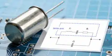
Resonant has very unique and robust Surface Acoustic Wave (SAW) with equal performance of the Bulk Acoustic Wave (BAW) types of filters.

Figure 2: This image shows the different ways to construct an acoustic resonator (Image courtesy of Reference 1)
Their designers us an Infinite Synthesized Networks (ISN) design method in developing a Band 3 duplexer by using low cost SAW processes that equal or exceed the performance of the BAW Band 3 duplexer—a more costly solution for the handset.
Power Amplifiers
In today’s RF design community, engineers have been able to design a single Power Amplifier (PA) which is capable of handling multiple technology modes like CDMA, LTE, W-CDMA and multiple frequencies and bands. This is the Multi-Mode/Multi-Band (MMMB) PA. A filter is needed for each RF path, so this adds to the extra cost in the handset.
The Infinite Synthesized Networks (ISN)
Resonant has managed to combine modern filter theory, finite element modeling for both Electro-Magnetic and Acoustic types, and an innovative set of optimization algorithms. Resonant’s very accurate filter models reflect the physical details of the filter structure which offers the actual filter performance in the areas of loss, isolation as well as in power handling capability and linearity.
Now designers are able to greatly reduce development time and complexity since the optimization can now be done on a computer instead of using high costs of multiple iterations in the fab. Another added benefit is the design and simulation of optimization of performance over many temperature ranges before producing a piece of hardware.
Designs can be optimized at higher power and higher temperatures such as that required by LTE, which operates at higher power than CDMA. Ultimately yield will be improved which in turn lowers the cost of production and brings a faster Return-on-Investment (ROI)
Other architectural choices
Reconfigurable Radios2
This architecture for the radio can increase the efficiency of spectrum usage as well as possibly lower cost in wireless handsets. Current multi-standard radios hardware and software architectures will not cut it when the next generation number of standards must greatly increase.
Software Defined Radios (SDR) have been suggested by some as a possible solution here. The problem with this solution is that it will require more heavy demands on the RF section and will need higher dynamic range and the SDR will have much higher power needs from the power supply. OK for a laptop computer but not for a handheld device. It may not even be possible to get the radio sensitivity needed to keep pace with current cellphones due to the high bandwidth demand.
Enter the reconfigurable radio that will be able to select multiple bands. This solution architecture will integrate tunable passive filters into the transceiver front end. See Figure 3.

Figure 3: This architecture shows a reconfigurable radio with tunable preselect filters. (a) is the Direct Conversion design and (b) is the RF bandpass sampling architecture. (Image courtesy of Reference 2)
The high dynamic range need is alleviated by Figure 3a because this architecture helps remove interferers and blocking signals near the signal of interest and thus RF circuit saturation will be less likely to happen in the low noise amplifier (LNA) or the mixer. The A to D converter (ADC) also does not need such a high dynamic range now as well so it can be simpler and lower cost.
Figure 3b has the RF sampling replacing the down-conversion block and many channels can be processed simultaneously. This approach, using tunable anti-aliasing filters in front of the ADC is the best power efficiency choice along with more versatility in reconfiguring the radio.
This technique; however, still leaves some challenges before they can be realistically implemented into the smart phones of the future. One problem is when using reconfigurable radio technology, what would the cost of an entrant’s license be to get wireless licenses for a national footprint? Will the FCC need to develop new auction protocol? Plus, there may be other support components needed besides tunable antennas and filters, switches and frequency synthesizers. And finally, what will the needed tuning speed be in order to maintain uninterrupted connectivity?
An alternate RF receiver design3
In the 5G Internet of Everything (IoE), cell phone users will need to get information on demand anytime, anywhere. This would be a battery life killer for a handheld battery-operated device. Reference 3 proposes an RF receiver design using a translational circuit in a different receiver architecture. A high-Q bandpass filter is developed for any RF frequency to help lower the RF receiver power consumption. The translational circuit is shown in Figure 4.

Figure 4: (a) is the translational circuit diagram, (b) is its frequency response and (c) is the time domain representation. (Image courtesy of Reference 3)
Translational circuits first appeared in the 1940s and it was resurrected because of the need for RF designers to generate high-Q bandpass filters at the LO frequency.
Up until now RF receivers for GSM and LTE high-performance needs were the targets for such an architecture. Now, would it be possible to further lower the power consumption while maintaining acceptable performance in LTE, LTE-A, and ultimately 5G? To be determined.
My money, at this juncture in time, is on a good SAW filter approach with low cost solutions such as Resonant has developed.
References
- Radically reducing the cost and size of cellphone RF filters to fuel the mobile revolution, Resonant Inc., June 30, 2015
- Reconfigurable Radios: A possible solution to reduce entry costs in wireless phones, M. Rais-Zadeh, D.D. Wentzloff, Y.B. Gianchandani, Proceedings of the IEEE, Vol. 103, No. 3, March 2015
- RF receiver design for IoE applications, JW Park, Qualcomm, IEEE ISOCC 2015