• Latest
  • Trending
  • All
  • Capacitors
  • Resistors
  • Inductors
  • Filters
  • Fuses
  • Non-linear Passives
  • Applications
  • Integrated Passives
  • Oscillators
  • Passive Sensors
  • New Technologies
  • Aerospace & Defence
  • Automotive
  • Industrial
  • Market & Supply Chain
  • Medical
  • RF & Microwave
  • Telecommunication

Best Practices & Advises for Antenna Tuning

23.3.2020

Würth Elektronik Announces Virtual Conference Digital WE Days 2023

22.9.2023

Circuit Protection Selection Guide 

22.9.2023

WT Microelectronics to Acquire Future Electronics

20.9.2023

Circuit Protection Components 2023 Market Analysis

20.9.2023

Ink-Jet Printed Flexible Capacitors: Manufacturing and Ageing Tests

19.9.2023

4th PCNS Awards Passive Component Papers

19.9.2023
  • Home
  • Privacy Policy
  • EPCI Membership & Advertisement
  • About
No Result
View All Result
NEWSLETTER
Passive Components Blog
  • Home
  • NewsFilter
    • All
    • Aerospace & Defence
    • Antenna
    • Applications
    • Automotive
    • Capacitors
    • Circuit Protection Devices
    • Filters
    • Fuses
    • Inductors
    • Industrial
    • Integrated Passives
    • Market & Supply Chain
    • Medical
    • New Materials & Supply
    • New Technologies
    • Non-linear Passives
    • Oscillators
    • Passive Sensors
    • Resistors
    • RF & Microwave
    • Telecommunication

    Circuit Protection Selection Guide 

    WT Microelectronics to Acquire Future Electronics

    Circuit Protection Components 2023 Market Analysis

    Ink-Jet Printed Flexible Capacitors: Manufacturing and Ageing Tests

    4th PCNS Awards Passive Component Papers

    Benefits of Ceramic Capacitors as Bootstrap Capacitors

    Vishay Boosts Power Inductor Manufacturing Capacity in Mexico

    SUMIDA to Build New Inductive Components Factory in Northern Vietnam

    Oscillators Integration, Selection Guide and Design In

    Trending Tags

    • Ripple Current
    • RF
    • Leakage Current
    • Tantalum vs Ceramic
    • Snubber
    • Low ESR
    • Feedthrough
    • Derating
    • Dielectric Constant
    • New Products
    • Market Reports
  • VideoFilter
    • All
    • Antenna videos
    • Capacitor videos
    • Filter videos
    • Fuse videos
    • Inductor videos
    • Non-linear passives videos
    • Oscillator videos
    • Passive sensors videos
    • Resistor videos
    • Sensors

    Oscillators Integration, Selection Guide and Design In

    Input Capacitor Selection for Power Supplies – Part 3: Electrolytic Capacitors

    Input Capacitor Selection for Power Supplies Part 2 – Ceramic Capacitors

    Input Capacitor Selection for Power Supplies Video (Part 1)

    Vishay Webinar: Components Selection for Solar Panel Systems

    Capacitors Basics: Decoupling

    Totem Pole PFC Design for E-Mobility; Microchip and WE Video

    High frequency model of the physical inductor: The Cauer model

    High frequency model of the physical inductor: The basic lumped model

    Trending Tags

    • Capacitors explained
    • Inductors explained
    • Resistors explained
    • Filters explained
    • Application Video Guidelines
    • EMC
    • New Products
    • Ripple Current
    • Simulation
    • Tantalum vs Ceramic
  • Knowledge Blog
  • Suppliers
    • Preferred Suppliers
    • Who is Who
  • Events
No Result
View All Result
Passive Components Blog
No Result
View All Result

Best Practices & Advises for Antenna Tuning

23.3.2020
Reading Time: 6 mins read
A A
75
VIEWS

Connectivity is key in today’s world and devices in the market require strong signal strength to allow for peak performance. Integrating an antenna is not trivial, whether it is an off-the-shelf product or a highly customized solution, and should not be an afterthought. AVX Ethertronics white paper discuss antenna design considerations.

The AVX antenna design team strongly recommends considering the antenna design and/or the antenna integration process as early as possible, ideally during the product design and the radio module selection. A perfect match between the radio and the antenna will ensure all wireless connectivity needs are met.

RelatedPosts

Würth Elektronik Announces Virtual Conference Digital WE Days 2023

Circuit Protection Selection Guide 

WT Microelectronics to Acquire Future Electronics

Metal Impact

In most cases, the vicinity of metallic elements is not the best fit for an antenna, unless it is used as a reflector. Indeed metallic surface will reflect all the RF power from the antenna, and as antennas are reciprocal, it also affects the power/waves that try to reach the antenna. Metallic surfaces are the enemy of free space propagation and this is why an antenna inside a metallic box without any openings will not radiate any power outside this box. Even though in many cases, the antenna needs help from its ground plane to perform, the proximity of any metallic elements around the antenna is to be avoided. Such components are heat sink, connectors, mirrors, B2B connectors, shield cans, other PCB with ground, ferrite beads and coils, big capacitors, battery and its battery connector, LCD/Display and its wire harness, other cables or wires…

LCD and batteries are considered like metallic elements in the antenna world, as well as their wire harnesses connected to the main PCB of the device. The location and size of the battery or LCD connector/wire might impact the antenna tuning too. Indeed, as the antenna converts electric signals into electromagnetic airwaves, it induces RF currents running on the ground of the device including the battery/display and its connectors or wires. Having RF currents running on the battery or the LCD can create constructive (currents going in one direction, used like a ground plane extension) or destructive interference (currents operating in a zigzag shape). LCD is also an important source of electromagnetic noise and besides the impact on the radiation pattern, it can add noise on the signal, degrading the sensitivity of the device.

Cable Routing and Grounding

It is highly recommended to route cables and wires far away from the antenna location and if possible, ground those cables at few locations on the main ground of the device. This grounding can be operated by laser processing the cable jacket and by soldering small clips at that location down to the main grounding.

Antenna Coupling

The proximity of other antennas is impacting the RF performances, especially if the other antenna operates in the same frequency bandwidth. There are tricks to improve isolation or coupling between two antennas. Ethertronics’ IMD technology allows two antennas to be located closer. Though, additional tricks can be used like slots in the grounding, reflector antennas added at specific locations, adding notch filters, making each antenna radiating with different polarization or making sure that the phase of each antenna signal is shifted by 90 degrees.

Cable Routing – Keep-out Area

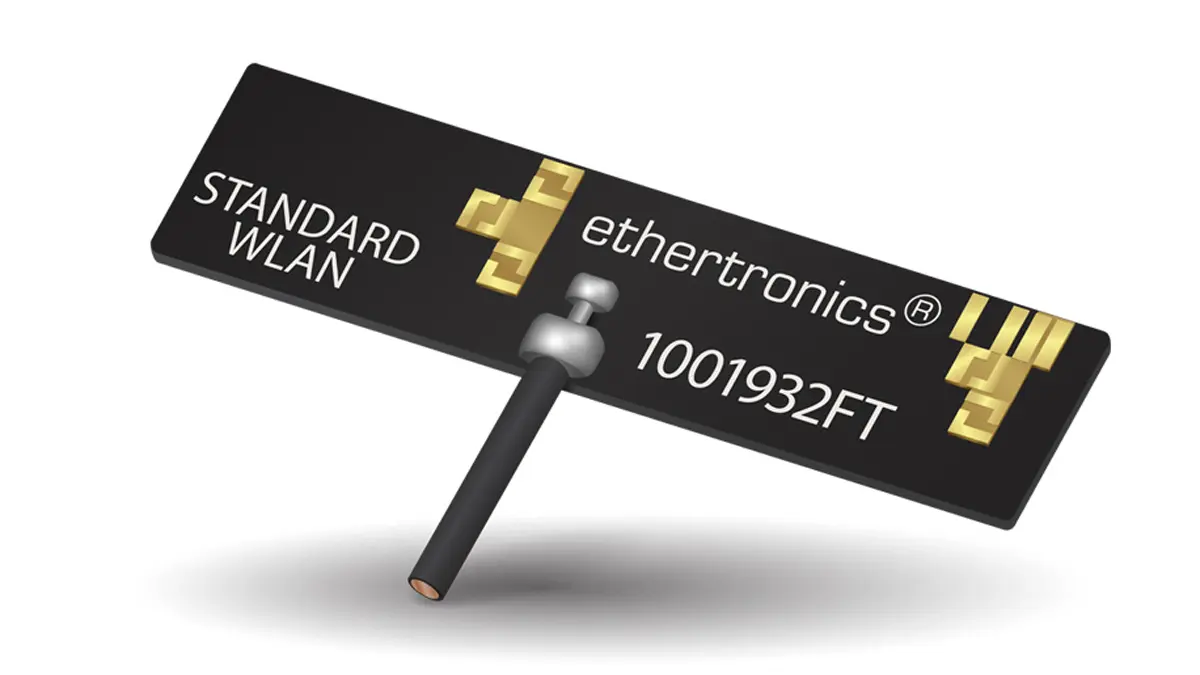
Off-board antennas are antennas connected to the radio with a cable, connector or harnesses in some sort. Any pigtail accessory from the antenna needs to be routed properly in order to interfere constructively with the antenna radiations. On-board antennas might or not require a keep-out area or called clearance area. It is better to follow the recommended clearance area from the antenna datasheet to maximize the antenna performance. the keep out area belongs to the tuning of the antenna as much as the antenna location and the dimensions of the PCB.

Interference with Printed Lines on the PCB

It is preferable to keep big distance (quarter wavelength) between the antenna and high speed digital lines. Those lines would act as antennas and would couple negatively the radiated RF power at a certain frequency, related to its equivalent quarter wavelength. Though it is possible to decouple those lines in order to reduce the coupling generated by using some inductors, which value vary between 80-150 nH, it is safer to keep those lines away.

Similarly, the DC lines feeding some motors, acoustic components like microphones, earpiece, speakers, vibrators can be dramatically impacting the RF performance of the antenna. Those lines can be decoupled up to a certain point with inductors placed on each lines.

Impact from Materials

Any material surrounding the antenna with a permittivity (loosely called Dielectric constant, Dk, Loss tangent) different from 1 (air permittivity is 1, water is 80) will affect the antenna tuning. Other parameters such as the distance from those materials to the antenna and the amount will play a role into defining the equivalent effective permittivity surrounding the antenna. Any plastic resins, epoxy resins, potting materials, laminated structures will all have non neglect-able RF losses applied to the radiation of the antenna.

Antenna Feed Line Design

An often taken for granted parameter is the design of the transition between the output of the radio and the input of the antenna feed. That transition must present the proper expected impedance (often 50 Oms) in order to optimize the reflection coefficient at the antenna input level. In the event that the design requires a Z0 characteristics impedance, it is possible to ask the lamination manufacturer to add TDR coupons on its laminated panel to detect the lines that are off by more than +/- 10% compared to the expected value.

PI Network

To ensure that the impedance of the antenna will match the output impedance of the radio, it is a good practice to always add one PI shape matching circuit foot print (3 components, SHUNT-SERIAL-SHUNT) that can be used to define the matching circuit that will maximize the power transfer to the antenna. If the PI shape matching circuit is not used, then a 0 Ohm resistor is can be soldered on the SERIAL component foot print and the SHUNT components foot print can be left OPEN.

Matching Network Recommendations

When Selecting the components for the Matching circuit, filtering or decoupling, it is mandatory that the SRF (Self Resonance Frequency) of the chosen components are compatible with the frequency of the radio signal. SRF depends of the components size, packaging and manufacturing technology. We recommend using the Accu-P® and Accu-L® thin films Capacitors and Inductors in order to get the most precise matching circuit.

Testing Cable

During the design of the PCB, it is a good practice to consider the possibility of soldering a semi rigid RF Cable to check the output of the RF radio or Antenna Impedance (for the debugging phase). To do that a non-assembled, three components T shape circuit SERIAL-SHUNT-SERIAL located before the antenna PI matching circuit (so the Matching circuit will be on the antenna and the soldered cable) is useful. The RF cable can be soldered on the SHUNT component footprint of the T-SHAPE and a 0 Ohm can be used to select the RF path either towards the radio or towards the antenna matching circuit.

Real Case Tuning Conditions

When designing antenna for Wearable product or for product that will be used in very specific condition, always tune the antenna for these real user cases (when the device is worn or in the specific position) instead of tuning the antenna in Free Space conditions.

Source: AVX

Related Posts

Sponsored

Würth Elektronik Announces Virtual Conference Digital WE Days 2023

22.9.2023
17
Circuit Protection Devices

Circuit Protection Selection Guide 

22.9.2023
15
Capacitors

Benefits of Ceramic Capacitors as Bootstrap Capacitors

19.9.2023
43

Upcoming Events

Sep 26
September 26 @ 12:00 - September 28 @ 14:00 EDT

Microwave Packaging Technology

Sep 26
16:00 - 17:00 CEST

Connector Temperature Rise and Derating

Oct 3
October 3 @ 12:00 - October 5 @ 14:00 EDT

Design and Test of Non-Hermetic Microelectronic

View Calendar

Popular Posts

  • What is a Dielectric Constant of Plastic Materials ?

    4 shares
    Share 4 Tweet 0
  • Understanding High-Precision Resistor Temperature Coefficient of Resistance

    0 shares
    Share 0 Tweet 0
  • Ripple Current and its Effects on the Performance of Capacitors

    3 shares
    Share 3 Tweet 0
  • Capacitor Selection for Coupling and Decoupling Applications

    28 shares
    Share 28 Tweet 0
  • Why Low ESR Matters in Capacitor Design

    0 shares
    Share 0 Tweet 0
  • Non-Linear Resistors: Thermistors, Varistors, Memristors

    0 shares
    Share 0 Tweet 0
  • Dielectric Constant and its Effects on the Properties of a Capacitor

    7 shares
    Share 7 Tweet 0
  • How to Choose the Right Inductor for DC-DC Buck Applications

    0 shares
    Share 0 Tweet 0

Newsletter Subscription


Archive

2023
2022
2021
2020
2019
2018
2017

Symposium

Passive Components Networking Symposium

Passives e-Learning

Knowledge Blog

  • Home
  • Privacy Policy
  • EPCI Membership & Advertisement
  • About

© EPCI - Premium Passive Components Educational and Information Site

No Result
View All Result
  • Home
  • News
  • Video
  • Knowledge Blog
  • Preferred Suppliers
  • Events

© EPCI - Premium Passive Components Educational and Information Site

This website uses cookies. By continuing to use this website you are giving consent to cookies being used. Visit our Privacy and Cookie Policy.