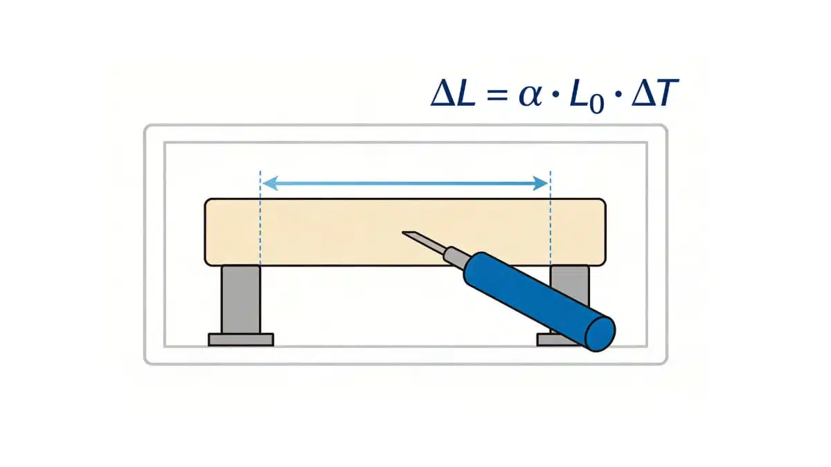
The Coefficient of Linear Thermal Expansion (CLTE) is a key design parameter for polymer-based parts, determining how plastics change dimensions with temperature and how they interact with metals, ceramics, and other materials in assemblies.
This article summarizes CLTE fundamentals, measurement methods, and typical values for a wide range of engineering plastics to support material selection and thermal modelling and its thermal modelling.
Key Takeaways
- The article provides a comprehensive overview of the Linear Thermal Expansion Coefficient (CLTE) for polymers, detailing how materials expand when heated.
- CLTE is crucial for assessing material stability under temperature changes and is important for production economics and product quality.
- The article explains calculation methods for CLTE and highlights key measurement techniques like dilatometry and thermomechanical analysis.
- Factors affecting CLTE include filler types, temperature, and molecular orientation, impacting how polymers behave under thermal stress.
- A table lists the linear thermal expansion values for various plastics, aiding in material selection for engineering applications.
mensions, to part war-page or to internal stress.
What Is the Linear Coefficient of Thermal Expansion?
The coefficient of thermal expansion (CTE) describes the fractional dimensional change of a material per degree of temperature change. When only length is considered, it is more precisely called the coefficient of linear thermal expansion (CLTE), usually denoted by α.
For a finite temperature interval, the mean linear coefficient of thermal expansion is:
Where:
- α is coefficient of linear thermal expansion per degree Celsius
- ΔL is change in length of test specimen due to heating or to cooling
- L0 is the original length of specimen at room temperature
- ΔT is temperature change, °C, during test
Because a temperature increment of 1 K equals an increment of 1 °C, values expressed in 10⁻⁶/K and 10⁻⁶/°C are numerically identical. The temperature interval must nevertheless always be reported.
For a continuously varying expansion curve, the differential or instantaneous CLTE is:
This distinction is important for polymers because their expansion is often nonlinear over a broad temperature range, particularly near the glass-transition temperature, Tg.
What happens when material is heated?
Under the effects of increasing temperature any material will expand. This can lead to significant changes in di
Therefore, α is obtained by dividing the linear expansion per unit length by the change in temperature. When reporting the mean coefficient of thermal expansion, the temperature ranges must be specified.
Temperature Dependence and the Glass-Transition Temperature
A polymer does not necessarily have one constant CLTE value. Its dimensional response depends on temperature, thermal history, morphology, filler system, and environmental condition.
For amorphous polymers and thermoset systems, CLTE commonly changes substantially at the glass-transition temperature, Tg. Below Tg, the material is in a relatively rigid glassy state and the coefficient is often reported as α1. Above Tg, molecular mobility increases and the coefficient is often reported as α2. In many systems, α2 is significantly higher than α1.
This distinction is critical in electronic assemblies. A polymer encapsulant, adhesive, PCB laminate, or connector housing may be relatively well matched to adjacent materials at normal operating temperature but become much less well matched during solder reflow, thermal shock, or high-temperature operation. Therefore, engineering calculations should use CLTE values from the actual temperature region of interest rather than a single room-temperature value.
For crystalline and semi-crystalline polymers, additional changes may occur near crystallization or melting transitions. Always check the supplier’s test interval, heating rate, sample conditioning, and whether the stated value applies below or above Tg.
Applications include:
The thermal expansion difference develops internal stresses and stress concentrations in the polymer, which allows premature failure to occur. Hence, CLTE is important for the economics of production as well as the quality and functioning of products.
Quick CLTE Calculation for Dimensional Change
For an unconstrained polymer feature, the approximate linear dimensional change can be calculated as:
ΔL = α × L0 × ΔT
Example: a 100 mm long polymer part has a mean CLTE of 80 × 10⁻⁶/°C and experiences a temperature rise from 20°C to 100°C.
ΔL = 80 × 10⁻⁶/°C × 100 mm × 80°C = 0.64 mm
The part would expand by approximately 0.64 mm if it were free to move.
In a real assembly, parts are often constrained by screws, solder joints, adhesive bonds, metal inserts, leadframes, or neighboring materials. Differential expansion can then create strain and stress rather than free movement. A first-order mismatch strain screen is:
εmismatch ≈ (α1 − α2) × ΔT
This expression is useful for comparing material combinations, but it is not a complete stress model. Reliable stress prediction also requires geometry, elastic modulus, Poisson’s ratio, creep or viscoelastic behavior, interfacial adhesion, assembly constraints, and the actual thermal profile.
Why CLTE Matters in Electronics Packaging and Passive Components
In electronics, CLTE mismatch is important wherever polymers, metals, ceramics, solder, and PCB laminates are joined in one mechanically constrained structure. Typical combinations include polymer connector housings with copper contacts and FR-4 boards; epoxy mold compounds or underfills with silicon dies and leadframes; polymer coatings and adhesives on ceramic components; and passive components soldered to PCB pads.
A temperature excursion causes each material to attempt a different dimensional change. If the assembly cannot accommodate this movement, thermo-mechanical stress is transferred into interfaces, solder joints, ceramic bodies, metallization layers, or polymer bonds. Repeated cycling can contribute to solder-joint fatigue, delamination, connector-contact displacement, PCB-via stress, and cracking of brittle ceramic components.
For connectors, compliant contact termination geometry can reduce the stress transferred to solder joints when a polymer housing expands more than the PCB. Read more in Soldering Technologies.
For multilayer ceramic capacitors, inductors, and chip beads, compliant or soft terminations can help absorb stress from board flexure and thermal cycling before it reaches the brittle ceramic body. See TDK Explains Soft Termination on Capacitors, Inductors and Chip Beads.
For chip resistors, the substrate, resistive element, protective coating, solder joints, and PCB expand differently during power cycling and ambient-temperature cycling. This is one reason why package size, board layout, local temperature gradient, and mounting design affect reliability. See SMD Chip Resistors: Types, Packages, Ratings and Reliability.
CLTE matching does not require identical values in every layer. The practical objective is to control differential expansion, provide compliant interfaces where necessary, avoid abrupt stiffness changes, and qualify the complete assembly under representative temperature cycling and soldering conditions.
How to Select Useful CLTE Data
Generic CLTE ranges are suitable for early material screening, but they should not be used as final design or simulation inputs. The same polymer family can have very different CLTE values depending on grade formulation and test conditions.
Before using a CLTE value for a component design, datasheet comparison, tolerance calculation, or FEM model, verify:
- Exact polymer grade, including flame-retardant package, reinforcement, mineral filler, and recycled-content status
- Filler type, loading, aspect ratio, and fibre orientation
- Specimen direction: flow/machine direction and transverse direction for molded or fibre-filled materials
- Temperature interval, especially whether the value is below Tg, above Tg, or averaged across Tg
- Measurement method, such as ASTM D696, ASTM E228, ASTM E831, or ISO 11359
- Specimen conditioning, moisture content, and prior thermal history
- Heating rate, number of specimens, and whether the published value is typical, minimum, maximum, or a guaranteed specification
For hygroscopic materials, especially many polyamides, moisture conditioning can also affect dimensions and measured behavior. Use the material supplier’s grade-specific datasheet or measure representative molded samples when reliability, tolerances, or simulation accuracy are important.
How to Measure Coefficient of Linear Thermal Expansion?
Most widely used standards to measure coefficient of linear thermal expansion in plastics (thermoplastics and thermosetting materials, filled or unfilled, in the form of sheet or molded parts) are ASTM D696, ASTM E831, ASTM E228 and ISO 11359.
The main techniques used for CTE measurements are:
- Dilatometry
- Interferometry and
- Thermomechanical analysis
(of course there exist several other methods as well, but they are not discussed here)
Dilatometry Technique
It is the widely used technique in which specimen is heated in a furnace and displacement of the ends of the specimen are transmitted to a sensor by means of push rod. Push rods may be of the vitreous silica type, the high-purity alumina type, or the isotropic graphite type.
ASTM D696 – This test method covers determination of the coefficient of linear thermal expansion for plastic materials having coefficients of expansion greater than 1 µm/(m.°C) by use of a vitreous silica dilatometer. The nature of most plastics and the construction of the dilatometer make −30 to +30°C (−22°F to +86°F) a convenient temperature range for linear thermal expansion measurements of plastics. This range covers the temperatures in which plastics are most commonly used.
ASTM E228 – This test method shall be used for temperatures other than −30°C to 30°C to determine linear thermal expansion of solid materials with a push-rod dilatometer
Thermomechanical Analysis (TMA)
The measurements are made using a thermomechanical analyzer consisting of a specimen holder and a probe that transmits changes in length to a transducer that translates movements of the probe into an electrical signal.
ASTM E831 (and ISO 11359-2) – These methods are applicable applicable to solid materials that exhibit sufficient rigidity over the test temperature range. The lower limit for CTE with this method is 5 × 10⁻⁶/K (2.8 × 10⁻⁶/°F), but it may be used at lower or negative expansion levels with decreased accuracy and precision. It is applicable to the temperature range from −120 to 900°C. The temperature range may be extended depending upon the instrumentation and calibration materials used.
Interferometry
With optical interference techniques, displacement of the specimen ends is measured in terms of the number of wavelengths of monochromatic light. Precision is significantly greater than with dilatometry, but because the technique relies on the optical reflectance of the specimen surface, interferometry is not used much above 700 °C (1290 °F).
ASTM E289 provides a standard method for linear thermal expansion of rigid solids with interferometry that is applicable from –150 to 700 °C (–240 to 1290 °F). It is is more applicable to materials having low or negative CTE in the range of <5 × 10⁻⁶/K (2.8 × 10⁻⁶/°F) or where only limited lengths of thickness of other higher expansion coefficient materials are available.
| Method | Typical use | Practical strengths | Key limitations |
|---|---|---|---|
| Vitreous-silica dilatometry | Conventional plastic measurements around ambient temperature | Established method; straightforward interpretation; suitable for ASTM D696 scope | ASTM D696 is limited to −30°C to +30°C and is not suitable as a broad-temperature polymer characterization method |
| Push-rod dilatometry | Wider temperature range and rigid bulk specimens | Suitable for measuring expansion outside ASTM D696’s temperature range | Contact force, specimen rigidity, calibration, and thermal gradients must be controlled |
| Thermomechanical analysis (TMA) | Small samples, temperature scanning, transition behavior | Useful for observing CLTE changes across temperature regions, including near Tg | Probe load, specimen geometry, softening, and test parameters can influence results |
| Optical interferometry | Low-CTE materials or high-precision displacement work | Very high displacement sensitivity | Surface requirements and specialist instrumentation limit routine use |
Factors Affecting Thermal Expansion Coefficient Measurements of Plastics
- Fibers and other fillers significantly reduce thermal expansion. The degree of anisotropy of the filler and the filler orientation pose great impact on the linear coefficient of thermal expansion
- W.r.t the temperature, the magnitude of the CTE increases with rising temperature
- Molecular orientation also affects the thermal expansion of plastics. The thermal expansion is often affected by the cooling time during processing. This is especially true with semi-crystalline polymers whose crystallization process requires time
Find commercial grades matching your mechanical properties target using “Property Search – CTE, Linear” filter in Omnexus Plastics Database:
Linear Coefficient of Thermal Expansion Values of Several Plastics
How to Use the Polymer CLTE Table
The following values are broad, indicative ranges intended for early-stage material comparison only. They are not universal constants for a polymer family and must not replace grade-specific supplier data or measurement of the actual molded part.
For filled and fibre-reinforced compounds, expect direction-dependent values. A molding compound may have a low CLTE along the primary fibre-flow direction but a much higher value transverse to flow. For electronics packaging, PCB hardware, connector housings, adhesives, encapsulants, and passive-component assemblies, use data measured over the relevant operating, soldering, or qualification temperature range.
The Coefficient of Linear Thermal Expansion (Or Linear Coefficient of Thermal Expansion) lies between (in the service temperature range for each case):
- Ca. 0.6 x 10⁻⁴ to 2.3 x 10⁻⁴ K-1 for most of the thermoplastics
- Ca. 0.2 x 10⁻⁴ to 0.6 x 10⁻⁴ K-1 for thermosets
| Polymer Name | Min Value (10-5 /°C) | Max Value (10-5 /°C) |
| ABS – Acrylonitrile Butadiene Styrene | 00 | 15.00 |
| ABS Flame Retardant | 6.00 | 9.00 |
| ABS High Heat | 6.00 | 10.00 |
| ABS High Impact | 6.00 | 13.00 |
| ABS/PC Blend – Acrylonitrile Butadiene Styrene/Polycarbonate Blend | 4.00 | 5.00 |
| ABS/PC Blend 20% Glass Fiber | 1.80 | 2.00 |
| ABS/PC Flame Retardant | 3.00 | 4.00 |
| ASA – Acrylonitrile Styrene Acrylate | 6.00 | 11.00 |
| ASA/PC Blend – Acrylonitrile Styrene Acrylate/Polycarbonate Blend | 7.00 | 9.00 |
| ASA/PC Flame Retardant | 7.00 | 8.00 |
| ASA/PVC Blend – Acrylonitrile Styrene Acrylate/Polyvinyl Chloride Blend | 0.00 | 9.00 |
| CA – Cellulose Acetate | 8.00 | 18.00 |
| CAB – Cellulose Acetate Butyrate | 10.00 | 17.00 |
| Celllulose Diacetate- Pearlescent Films | 2.15 | 2.15 |
| Celllulose Diacetate-Gloss Film | 2.15 | 2.15 |
| Celllulose Diacetate-Integuard Films | 1.00 | 1.50 |
| Celllulose Diacetate-Matt Film | 2.15 | 2.15 |
| Cellulose Diacetate -Window Patch Film (Food Grade) | 2.15 | 2.15 |
| Cellulose Diacetate-Clareflect metallized film | 1.50 | 1.50 |
| Cellulose diacetate-Flame retardant Film | 0.64 | 0.64 |
| Cellulose Diacetate-High Slip Film | 2.15 | 2.15 |
| Cellulose Diacetate-High Slip Film | 2.15 | 2.15 |
| CP – Cellulose Proprionate | 10.00 | 17.00 |
| COC – Cyclic Olefin Copolymer | 6.00 | 7.00 |
| CPVC – Chlorinated Polyvinyl Chloride | 6.00 | 8.00 |
| CTFE | 6.00 | 9.00 |
| EVA – Ethylene Vinyl Acetate | 16.00 | 20.00 |
| FEP – Fluorinated Ethylene Propylene | 8.00 | 10.00 |
| HDPE – High Density Polyethylene | 6.00 | 11.00 |
| HIPS – High Impact Polystyrene | 5.00 | 20.00 |
| HIPS Flame Retardant V0 | 5.00 | 15.00 |
| Ionomer (Ethylene-Methyl Acrylate Copolymer) | 10.00 | 17.00 |
| LCP – Liquid Crystal Polymer | 0.30 | 7.00 |
| LCP Carbon Fiber-reinforced | 0.10 | 6.00 |
| LCP Glass Fiber-reinforced | 0.10 | 6.00 |
| LCP Mineral-filled | 0.90 | 8.00 |
| LDPE – Low Density Polyethylene | 10.00 | 20.00 |
| MABS (Transparent Acrylonitrile Butadiene Styrene) | 8.00 | 11.00 |
| PA 11 – (Polyamide 11) 30% Glass fiber reinforced | 3.00 | 15.00 |
| PA 11, Conductive | 9.00 | 15.00 |
| PA 11, Flexible | 9.00 | 15.00 |
| PA 11, Rigid | 9.00 | 15.00 |
| PA 12 (Polyamide 12), Conductive | 9.00 | 15.00 |
| PA 12, Fiber-reinforced | 9.00 | 15.00 |
| PA 12, Flexible | 9.00 | 15.00 |
| PA 12, Glass Filled | 9.00 | 15.00 |
| PA 12, Rigid | 9.00 | 15.00 |
| PA 46, 30% Glass Fiber | 2.00 | 2.00 |
| PA 6 – Polyamide 6 | 5.00 | 12.00 |
| PA 6-10 – Polyamide 6-10 | 6.00 | 10.00 |
| PA 66 – Polyamide 6-6 | 5.00 | 14.00 |
| PA 66, 30% Glass Fiber | 2.00 | 3.00 |
| PA 66, 30% Mineral filled | 4.00 | 5.00 |
| PA 66, Impact Modified, 15-30% Glass Fiber | 2.00 | 3.00 |
| PA 66, Impact Modified | 5.00 | 14.00 |
| PAI – Polyamide-Imide | 3.00 | 4.00 |
| PAI, 30% Glass Fiber | 1.00 | 2.00 |
| PAI, Low Friction | 2.00 | 3.00 |
| PAN – Polyacrylonitrile | 6.00 | 7.00 |
| PAR – Polyarylate | 5.00 | 8.00 |
| PARA (Polyarylamide), 30-60% glass fiber | 1.40 | 1.80 |
| PBT – Polybutylene Terephthalate | 6.00 | 10.00 |
| PBT, 30% Glass Fiber | 2.00 | 5.00 |
| PC (Polycarbonate) 20-40% Glass Fiber | 2.00 | 4.00 |
| PC (Polycarbonate) 20-40% Glass Fiber Flame Retardant | 2.00 | 4.00 |
| PC – Polycarbonate, high heat | 7.00 | 9.00 |
| PCL – Polycaprolactone | 16.00 | 17.00 |
| PCTFE – Polymonochlorotrifluoroethylene | 4.00 | 7.00 |
| PE – Polyethylene 30% Glass Fiber | 5.00 | 5.00 |
| PEEK – Polyetheretherketone | 4.70 | 10.80 |
| PEEK 30% Carbon Fiber-reinforced | 1.50 | 1.50 |
| PEEK 30% Glass Fiber-reinforced | 1.50 | 2.20 |
| PEI – Polyetherimide | 5.00 | 6.00 |
| PEI, 30% Glass Fiber-reinforced | 2.00 | 2.00 |
| PEI, Mineral Filled | 2.00 | 5.00 |
| PEKK (Polyetherketoneketone), Low Cristallinity Grade | 77.00 | 77.00 |
| PESU – Polyethersulfone | 5.00 | 6.00 |
| PESU 10-30% glass fiber | 2.00 | 3.00 |
| PET – Polyethylene Terephtalate | 6.00 | 8.00 |
| PET, 30% Glass Fiber-reinforced | 2.00 | 5.00 |
| PET, 30/35% Glass Fiber-reinforced, Impact Modified | 1.50 | 2.00 |
| PETG – Polyethylene Terephtalate Glycol | 8.00 | 8.00 |
| PFA – Perfluoroalkoxy | 8.00 | 12.00 |
| PI – Polyimide | 5.50 | 5.50 |
| PLA – Polylactide | 8.50 | 8.50 |
| PMMA – Polymethylmethacrylate/Acrylic | 5.00 | 9.00 |
| PMMA (Acrylic) High Heat | 4.00 | 9.00 |
| PMMA (Acrylic) Impact Modified | 5.00 | 9.00 |
| POM – Polyoxymethylene (Acetal) | 10.00 | 15.00 |
| POM (Acetal) Impact Modified | 12.00 | 13.00 |
| POM (Acetal) Low Friction | 10.00 | 12.00 |
| POM (Acetal) Mineral Filled | 8.00 | 9.00 |
| PP – Polypropylene 10-20% Glass Fiber | 4.00 | 7.00 |
| PP, 10-40% Mineral Filled | 3.00 | 6.00 |
| PP, 10-40% Talc Filled | 4.00 | 8.00 |
| PP, 30-40% Glass Fiber-reinforced | 2.00 | 3.00 |
| PP (Polypropylene) Copolymer | 7.00 | 17.00 |
| PP (Polypropylene) Homopolymer | 6.00 | 17.00 |
| PP, Impact Modified | 7.00 | 17.00 |
| PPA – Polyphthalamide | 5.40 | 5.40 |
| PPA, 30% Mineral-filled | 7.10 | 7.20 |
| PPA, 33% Glass Fiber-reinforced | 1.00 | 1.20 |
| PPA, 33% Glass Fiber-reinforced – High Flow | 0.90 | 1.10 |
| PPA, 45% Glass Fiber-reinforced | 0.73 | 0.75 |
| PPE – Polyphenylene Ether | 3.00 | 7.00 |
| PPE, 30% Glass Fiber-reinforced | 1.50 | 2.50 |
| PPE, Flame Retardant | 3.00 | 7.00 |
| PPE, Impact Modified | 4.00 | 8.00 |
| PPE, Mineral Filled | 2.00 | 5.00 |
| PPS – Polyphenylene Sulfide | 3.00 | 5.00 |
| PPS, 20-30% Glass Fiber-reinforced | 1.00 | 4.00 |
| PPS, 40% Glass Fiber-reinforced | 1.00 | 3.00 |
| PPS, Conductive | 1.00 | 9.00 |
| PPS, Glass fiber & Mineral-filled | 1.00 | 2.00 |
| PS (Polystyrene) 30% glass fiber | 3.50 | 3.50 |
| PS (Polystyrene) Crystal | 5.00 | 8.00 |
| PS, High Heat | 6.00 | 8.00 |
| PSU – Polysulfone | 5.00 | 6.00 |
| PSU, 30% Glass fiber-reinforced | 2.00 | 3.00 |
| PSU Mineral Filled | 3.00 | 4.00 |
| PTFE – Polytetrafluoroethylene | 7.00 | 20.00 |
| PTFE, 25% Glass Fiber-reinforced | 7.00 | 10.00 |
| PVC (Polyvinyl Chloride), 20% Glass Fiber-reinforced | 2.00 | 4.00 |
| PVC, Plasticized | 5.00 | 20.00 |
| PVC, Plasticized Filled | 7.00 | 25.00 |
| PVC Rigid | 5.00 | 18.00 |
| PVDC – Polyvinylidene Chloride | 10.00 | 20.00 |
| PVDF – Polyvinylidene Fluoride | 8.00 | 15.00 |
| SAN – Styrene Acrylonitrile | 6.00 | 8.00 |
| SAN, 20% Glass Fiber-reinforced | 2.00 | 4.00 |
| SMA – Styrene Maleic Anhydride | 7.00 | 8.00 |
| SMA, 20% Glass Fiber-reinforced | 2.00 | 4.00 |
| SMA, Flame Retardant V0 | 2.00 | 6.00 |
| SRP – Self-reinforced Polyphenylene | 3.00 | 3.00 |
| UHMWPE – Ultra High Molecular Weight Polyethylene | 13.00 | 20.00 |
| XLPE – Crosslinked Polyethylene | 10.00 | 10.00 |
CLTE Design Checklist for Electronic Assemblies
- Define the full temperature profile: storage, operating, self-heating, solder reflow, thermal shock, and qualification cycling.
- Identify every mechanically coupled material: polymer, ceramic, metal, solder, adhesive, coating, and PCB laminate.
- Obtain grade-specific and direction-specific CLTE data over the relevant temperature intervals.
- Check whether a polymer, laminate, or adhesive crosses Tg during manufacturing or use.
- Calculate free dimensional change as an initial screen, then evaluate differential expansion at constrained interfaces.
- Consider compliant features such as flexible leads, contact geometry, soft terminations, adhesive thickness, or strain-relief structures where brittle materials are involved.
- Assess moisture conditioning and thermal ageing where hygroscopic or moisture-sensitive polymer systems are used.
- Validate the complete assembly with representative soldering, temperature-cycling, thermal-shock, vibration, and mechanical-loading tests as appropriate.
Conclusion
The coefficient of linear thermal expansion is a fundamental material property for predicting dimensional stability and thermo-mechanical compatibility of polymer parts. For practical engineering use, however, CLTE should never be treated as a single universal number.
A useful CLTE value must be linked to the exact material grade, filler system, specimen direction, moisture condition, measurement method, and temperature interval. This is particularly important near the glass-transition temperature, where polymer expansion behavior can change substantially.
In electronic assemblies, CLTE mismatch between polymers, PCB laminates, metals, solder, ceramics, adhesives, and encapsulants can drive warpage, delamination, solder-joint fatigue, contact displacement, and cracking. Early material screening with indicative values is useful, but final tolerance analysis, reliability assessment, and thermo-mechanical simulation should use grade-specific data and representative assembly-level validation.
References
- SpecialChem Omnexus, “Coefficient of Linear Thermal Expansion (CTE, Linear) of Plastics,”
- ASTM International, “ASTM D696 – Standard Test Method for Coefficient of Linear Thermal Expansion of Plastics Between −30°C and 30°C with a Vitreous Silica Dilatometer,”
- ASTM International, “ASTM E831 – Standard Test Method for Linear Thermal Expansion of Solid Materials by Thermomechanical Analysis,”
- ASTM International, “ASTM E228 – Standard Test Method for Linear Thermal Expansion of Solid Materials with a Push‑Rod Dilatometer,”
- ASTM International, “ASTM E289 – Standard Test Method for Linear Thermal Expansion of Rigid Solids with Interferometry,”
- ISO, “ISO 11359 – Plastics — Thermomechanical analysis (TMA) — Determination of coefficient of linear thermal expansion and glass transition temperature,”
FAQ: Coefficient of Linear Thermal Expansion on Polymers
The Coefficient of Linear Thermal Expansion (CLTE), often denoted as α, describes how much a polymer expands per unit length when exposed to a change in temperature. It is calculated as α = ΔL / (L₀ × ΔT).
CLTE is critical for predicting dimensional stability, shrinkage in injection molding, and thermal stresses in multi-material assemblies. It directly impacts product reliability, bonding efficiency, and long-term performance.
The most common standards include ASTM D696, ASTM E831, ASTM E228, and ISO 11359. These define methods such as dilatometry, thermomechanical analysis (TMA), and interferometry.
Fillers, fiber orientation, molecular structure, and processing conditions (like cooling time) significantly influence CLTE values. For example, glass fiber reinforcement reduces expansion dramatically.
How-to: Measure the Coefficient of Linear Thermal Expansion in Polymers
- Prepare the specimen
Cut a polymer sample to standard dimensions and record its initial length (L₀) at room temperature.
- Select the measurement method
Choose between dilatometry, thermomechanical analysis (TMA), or interferometry depending on the required precision and temperature range.
- Apply controlled heating
Gradually heat the specimen within the defined test range (e.g., −30°C to +30°C for ASTM D696) while monitoring dimensional changes.
- Record dimensional change
Measure the change in length (ΔL) using the selected method’s sensor or probe system.
- Calculate CLTE
Use the formula α = ΔL / (L₀ × ΔT) to determine the coefficient of linear thermal expansion. Report results with the applicable temperature range.