Passive Components Blog
No Result
View All Result
  • Home
  • NewsFilter
    • All
    • Aerospace & Defence
    • Antenna
    • Applications
    • Automotive
    • Capacitors
    • Circuit Protection Devices
    • electro-mechanical news
    • Filters
    • Fuses
    • Inductors
    • Industrial
    • Integrated Passives
    • inter-connect news
    • Market & Supply Chain
    • Market Insights
    • Medical
    • Modelling and Simulation
    • New Materials & Supply
    • New Technologies
    • Non-linear Passives
    • Oscillators
    • Passive Sensors News
    • Resistors
    • RF & Microwave
    • Telecommunication
    • Weekly Digest

    Littelfuse Announced TVS Diodes for 48 V Automotive Systems

    Spectrum Controls Joins Modelithics Program to Offer High‑Fidelity RF Models for Resistors, Attenuators and Terminations

    RF Filters and Passive Components Enabling the 7 Missile RF Subsystems

    Ferrite versus Nanocrystalline Power Inductor Cores: Turns, Gap and Size

    YAGEO Presents NANOMET Soft Magnetic Cores for High‑Density Power Conversion

    Coilcraft Releases High-Current Ferrite Beads for CISPR 25 EMC compliance

    From DCL to SSC: Bridging Electrical Symptoms and Structural Indicators in Tantalum Capacitors

    Vishay Unveils Multi-Turn Position Sensor for Harsh Industrial Environments

    YAGEO Introduces Automotive MOV Surge Protection Varistor

    Trending Tags

    • Ripple Current
    • RF
    • Leakage Current
    • Tantalum vs Ceramic
    • Snubber
    • Low ESR
    • Feedthrough
    • Derating
    • Dielectric Constant
    • New Products
    • Market Reports
  • VideoFilter
    • All
    • Antenna videos
    • Capacitor videos
    • Circuit Protection Video
    • Filter videos
    • Fuse videos
    • Inductor videos
    • Inter-Connect Video
    • Non-linear passives videos
    • Oscillator videos
    • Passive sensors videos
    • Resistor videos

    Ferrite versus Nanocrystalline Power Inductor Cores: Turns, Gap and Size

    KYOCERA AVX Presents Antenna Integrator Studio Tutorial for Antenna Placement and RF Design

    Power Design Simulation Tools for Faster Inductor Selection and Loss Optimization

    EMC‑Compliant PCB and Connector Design Guidelines

    Why Isolated DC/DC Power Supplies Fail Late, Würth Elektronik Podcast

    Designing 800 V DC EMC Filters: Calculation, Simulation and Measurement

    Current Sense Transformer Datasheet and Design‑in Guide

    Designing a USB Type‑C Flyback Planar Transformer with Frenetic’s Planar Tool

    Magnetics Design in High‑Frequency GaN Converters

    Trending Tags

    • Capacitors explained
    • Inductors explained
    • Resistors explained
    • Filters explained
    • Application Video Guidelines
    • EMC
    • New Products
    • Ripple Current
    • Simulation
    • Tantalum vs Ceramic
  • Knowledge Blog
  • Dossiers
    • AI Hardware Dossier
    • Power Converter Dossier
    • Automotive Dossier
    • Capacitor Dossier
    • Resistor Dossier
    • Inductor Dossier
    • Circuit Protection Dossier
  • Suppliers
    • Who is Who
  • PCNS
    • PCNS 2025
    • PCNS 2023
    • PCNS 2021
    • PCNS 2019
    • PCNS 2017
  • Events
  • Home
  • NewsFilter
    • All
    • Aerospace & Defence
    • Antenna
    • Applications
    • Automotive
    • Capacitors
    • Circuit Protection Devices
    • electro-mechanical news
    • Filters
    • Fuses
    • Inductors
    • Industrial
    • Integrated Passives
    • inter-connect news
    • Market & Supply Chain
    • Market Insights
    • Medical
    • Modelling and Simulation
    • New Materials & Supply
    • New Technologies
    • Non-linear Passives
    • Oscillators
    • Passive Sensors News
    • Resistors
    • RF & Microwave
    • Telecommunication
    • Weekly Digest

    Littelfuse Announced TVS Diodes for 48 V Automotive Systems

    Spectrum Controls Joins Modelithics Program to Offer High‑Fidelity RF Models for Resistors, Attenuators and Terminations

    RF Filters and Passive Components Enabling the 7 Missile RF Subsystems

    Ferrite versus Nanocrystalline Power Inductor Cores: Turns, Gap and Size

    YAGEO Presents NANOMET Soft Magnetic Cores for High‑Density Power Conversion

    Coilcraft Releases High-Current Ferrite Beads for CISPR 25 EMC compliance

    From DCL to SSC: Bridging Electrical Symptoms and Structural Indicators in Tantalum Capacitors

    Vishay Unveils Multi-Turn Position Sensor for Harsh Industrial Environments

    YAGEO Introduces Automotive MOV Surge Protection Varistor

    Trending Tags

    • Ripple Current
    • RF
    • Leakage Current
    • Tantalum vs Ceramic
    • Snubber
    • Low ESR
    • Feedthrough
    • Derating
    • Dielectric Constant
    • New Products
    • Market Reports
  • VideoFilter
    • All
    • Antenna videos
    • Capacitor videos
    • Circuit Protection Video
    • Filter videos
    • Fuse videos
    • Inductor videos
    • Inter-Connect Video
    • Non-linear passives videos
    • Oscillator videos
    • Passive sensors videos
    • Resistor videos

    Ferrite versus Nanocrystalline Power Inductor Cores: Turns, Gap and Size

    KYOCERA AVX Presents Antenna Integrator Studio Tutorial for Antenna Placement and RF Design

    Power Design Simulation Tools for Faster Inductor Selection and Loss Optimization

    EMC‑Compliant PCB and Connector Design Guidelines

    Why Isolated DC/DC Power Supplies Fail Late, Würth Elektronik Podcast

    Designing 800 V DC EMC Filters: Calculation, Simulation and Measurement

    Current Sense Transformer Datasheet and Design‑in Guide

    Designing a USB Type‑C Flyback Planar Transformer with Frenetic’s Planar Tool

    Magnetics Design in High‑Frequency GaN Converters

    Trending Tags

    • Capacitors explained
    • Inductors explained
    • Resistors explained
    • Filters explained
    • Application Video Guidelines
    • EMC
    • New Products
    • Ripple Current
    • Simulation
    • Tantalum vs Ceramic
  • Knowledge Blog
  • Dossiers
    • AI Hardware Dossier
    • Power Converter Dossier
    • Automotive Dossier
    • Capacitor Dossier
    • Resistor Dossier
    • Inductor Dossier
    • Circuit Protection Dossier
  • Suppliers
    • Who is Who
  • PCNS
    • PCNS 2025
    • PCNS 2023
    • PCNS 2021
    • PCNS 2019
    • PCNS 2017
  • Events
No Result
View All Result
Passive Components Blog
No Result
View All Result

Dielectric properties: why they’re important and how to measure them

23.6.2017
Reading Time: 5 mins read
A A

source: Electropages article

Keysight Technologies’ Giovanni D’Amore explains six methods of measuring this vital material characteristic.

RelatedPosts

Littelfuse Announced TVS Diodes for 48 V Automotive Systems

Spectrum Controls Joins Modelithics Program to Offer High‑Fidelity RF Models for Resistors, Attenuators and Terminations

RF Filters and Passive Components Enabling the 7 Missile RF Subsystems

Have you heard of dielectric properties? If you have, you’re probably thinking back to charge storage experiments you did in physics lessons at school. You might also have come across them when analysing the way dielectric materials affect a capacitor’s characteristics. But, contrary to their perceived niche status, dielectric properties are important in many ways across many sectors. It’s therefore vital to be able to measure them accurately.

Below, we’ll outline a range of use cases, and look at six ways to measure dielectric properties, explaining when you might use each one.

Dielectric properties: a breadth of use cases

We’ve already established that dielectric properties are important in the electronics industry when it comes to capacitor performance. Electronics engineers are also interested in dielectric properties of substrates, and the printed circuit boards (PCBs) they create with them. Furthermore, dielectric properties play a role when making antennas using PCB traces, when creating ‘phantom’ materials for systems that measure specific absorption rates, when working with absorbers, and when managing the propagation of electromagnetic fields by applying ferrite materials.

Those working in defence and aerospace will also be concerned with dielectric properties, particularly when it comes to developing stealth technology, radomes and materials that absorb radiation.

Across various industries, manufacturers need ways of characterising materials. This includes composite and ceramic materials for car parts; plastics and polymers for insulation, films and fibres; hydrogels used in soft contact lenses and nappies; and liquid crystal found in displays.

In the food sector, dielectric properties are an important measurement technique, used in the creation of microwaveable food when researching spoilage, moisture and packaging.

In forestry, dielectric measurements are used to identify how much moisture is contained in wood and paper, while in mining, they help analyse the contents of oil.

Elsewhere, these properties are used in the pharmaceutical industries to support drug research and manufacturing. Human tissue characterisation, fermentation and biomass system design and bio-implant research are all areas that take advantage of the technique.

Measuring dielectric properties

There are different ways to measure dielectric properties, with each using precise instruments, fixtures to hold the material under test (MUT) and software that helps you measure complex permittivity and permeability factors, and then shows the results.

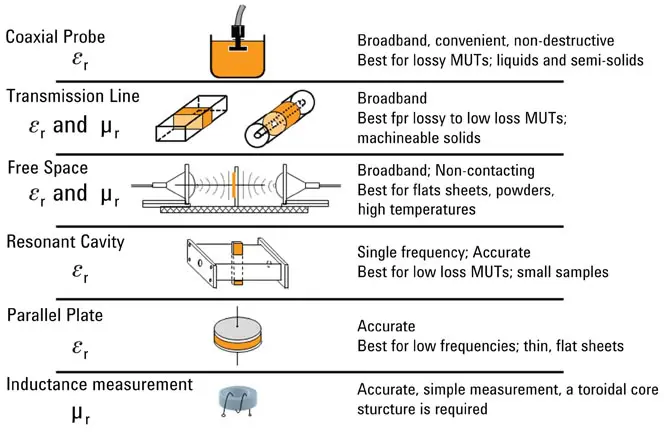
There are a range of products in this space, including impedance analysers, network analysers and LCR meters able to deliver accurate results when you apply frequencies up to 1.5 THz. Complementing these are fixtures that enable you to use the coaxial probe, coaxial/waveguide transmission line, free space, resonant cavity and parallel plate measurement techniques, which are shown in Figure 1 and described further below.


Fig1-Measuring-dielectric-properties
 

Figure 1: There are different ways to measure a material’s dielectric properties. (Source: Keysight Technologies)


So how do these measurement techniques work, and when might you use them?

Coaxial probe method

This technique is best for semi-solid materials (powders) and liquids. It’s non-destructive, straightforward and only requires a single measurement. A typical coaxial probe measurement system is made up of a network or impedance analyser, coaxial probe and appropriate software.

Choose your analyser and probe based on your measuring frequency, though the overall range is between 10M Hz and 50 GHz. You can also get probes that can withstand temperatures from -40°C to +200°C. These can be produced with a big flange, meaning you can also measure flat solid materials. There are slim probes available too, which are particularly helpful for taking measurements in chemical reaction chambers, fermentation tanks and other environments with small openings. For the medical, chemical and food sectors, there are high-performance probes that blend many of the above characteristics with the ability to be sterilised in an autoclave.


Fig2-Dielectric-probes
 

Figure 2: Different kinds of dielectric probe equipment (Source: Keysight Technologies)


Transmission line method

This broadband technique is designed for machinable solids. The MUT sits within an enclosed transmission line, and the frequency coverage is primarily restricted by the size of the sample holder.

Free space method

This non-contact technique uses antennas to direct microwave energy through or on to a material. You can use this method at high temperatures and at millimetre-wave frequencies.

Resonant cavity method

A resonant cavity is a high Q structure that will resonate at particular frequencies. When you introduce the MUT, this impacts on the centre frequency and Q factor of the cavity. This enables you to calculate its permittivity. Keysight makes a range of resonators, including the 85072A 10-GHz split-cylinder resonator and split-post dielectric resonators.

Parallel-plate capacitor method

This is the technique you might remember from school physics lessons. You create a capacitor by sandwiching a thin piece of your material between two electrodes. The parallel-plate capacitor method is ideal for achieving accurate, low-frequency measurements of liquids or thin sheets of material, typically using an impedance analyser or LCR meter.

Inductance measurement method

Finally, there’s the inductance measurement method, which measures a material’s inductance as though it were a toroidal core, thereby enabling you to derive its permeability. You wrap wire around the MUT and evaluate its inductance with respect to the wire ends. Keysight’s 16454A magnetic material test fixture is a good structure to use with single-turn inductors, because it won’t leak flux when you put a toroidal core into it.

The figure below shows the different testing approaches and types of fixture against the materials you’re testing and your measurement frequency.


Fig3-Keysight-probes-measurement-techniques
 

Figure 3: Different probes and measurement techniques enable you to measure a variety of materials at a range of test frequencies. (Source: Keysight Technologies)
 

Supporting software

Interpreting dielectric measurements as permeability and permittivity measurements can sometimes be difficult, but you can make your life easier by using software such as Keysight’s N1500A materials measurement suite. This helps you work with a network analyser, and guides you through the testing process, from set-up and measurement to transforming the resulting S-parameter data into the formats you require.

Because it works with a range of measurement techniques and mathematical models, the software can be used in most situations. You can also use it to model potential interactions between the MUT and the fixture, enabling you to extract bulk material properties.

The screenshot below shows how you define the MUT in relation to the fixture holding it in place. So-called ‘de-embedding’ enables you to cover one or both sides of your sample with dielectric backing. De-embedding mathematically eradicates the effect of the backing material, meaning you’re left solely with the electromagnetic properties of the sample. This technique is ideal when the sample isn’t able to stand by itself, or is attached to a substrate.


 

Fig4-software
Figure 4: Specialist software enables you to define your sample holder and use a technique called de-embedding. (Source: Keysight Technologies)


Related

Recent Posts

Littelfuse Announced TVS Diodes for 48 V Automotive Systems

10.7.2026
10

RF Filters and Passive Components Enabling the 7 Missile RF Subsystems

9.7.2026
35

Coilcraft Releases High-Current Ferrite Beads for CISPR 25 EMC compliance

8.7.2026
36

From DCL to SSC: Bridging Electrical Symptoms and Structural Indicators in Tantalum Capacitors

7.7.2026
46

Vishay Unveils Multi-Turn Position Sensor for Harsh Industrial Environments

7.7.2026
29

YAGEO Introduces Automotive MOV Surge Protection Varistor

7.7.2026
24

TDK Releases Compact SMD Gate Drive Transformers for xEV

7.7.2026
34

High-Q RF & Microwave MLCCs: A Cross-Vendor Benchmark

2.7.2026
78

TAIYO YUDEN Introduced Hybrid Aluminum Capacitors for 48V Automotive Power Supplies

2.7.2026
70

Upcoming Events

Jul 14
16:00 - 17:00 CEST

EMC Design Essentials: Mastering Varistors and Common Mode Chokes

Jul 21
16:00 - 17:00 CEST

Safety by design: X and Y Interference suppression capacitors for power line filters

Jul 28
8:00 - 11:00 CEST

Post Procurement Testing of EEE Components for LEO Space Applications

View Calendar

Popular Posts

  • Boost Converter Design and Calculation

    0 shares
    Share 0 Tweet 0
  • Buck Converter Design and Calculation

    0 shares
    Share 0 Tweet 0
  • Flyback Converter Design and Calculation

    0 shares
    Share 0 Tweet 0
  • LLC Resonant Converter Design and Calculation

    0 shares
    Share 0 Tweet 0
  • YAGEO Announces July 2026 Capacitor Price Increase

    0 shares
    Share 0 Tweet 0
  • MLCC and Ceramic Capacitors

    0 shares
    Share 0 Tweet 0
  • Earthing Systems and IEC Classification Explained

    0 shares
    Share 0 Tweet 0
  • Nvidia Vera Rubin: Why One AI Rack Needs So Many More MLCC Capacitors

    0 shares
    Share 0 Tweet 0
  • MLCCs in the Age of AI: Q2 2026 Market Tightness

    0 shares
    Share 0 Tweet 0
  • Dual Active Bridge (DAB) Topology

    0 shares
    Share 0 Tweet 0

Newsletter Subscription


Passive Components Blog

© EPCI - Leading Passive Components Educational and Information Site

  • Home
  • Privacy Policy
  • EPCI Membership & Advertisement
  • About

No Result
View All Result
  • Home
  • Knowledge Blog
  • Dossiers
  • PCNS

© EPCI - Leading Passive Components Educational and Information Site

This website uses cookies. By continuing to use this website you are giving consent to cookies being used. Visit our Privacy and Cookie Policy.
Go to mobile version