Passive Components Blog
No Result
View All Result
  • Home
  • NewsFilter
    • All
    • Aerospace & Defence
    • Antenna
    • Applications
    • Automotive
    • Capacitors
    • Circuit Protection Devices
    • electro-mechanical news
    • Filters
    • Fuses
    • Inductors
    • Industrial
    • Integrated Passives
    • inter-connect news
    • Market & Supply Chain
    • Market Insights
    • Medical
    • Modelling and Simulation
    • New Materials & Supply
    • New Technologies
    • Non-linear Passives
    • Oscillators
    • Passive Sensors News
    • Resistors
    • RF & Microwave
    • Telecommunication
    • Weekly Digest

    Samsung Electro-Mechanics Releases High-Capacitance MLCCs for AI Server Applications

    Samsung Electro-Mechanics Releases 165C Automotive 0806 Size Power Inductors

    Coupled Inductors Circuit Model and Examples of its Applications

    Würth Elektronik Introduces LTspice Models for ESD Products

    Capacitor Ripple Current Testing: A Design Consideration

    TDK Releases 0201 High-Frequency Smallest Inductors

    Coilcraft Extends Air Core RF Inductors

    Bourns Releases Automotive 1W Flyback Transformer

    Wk 20 Electronics Supply Chain Digest

    Trending Tags

    • Ripple Current
    • RF
    • Leakage Current
    • Tantalum vs Ceramic
    • Snubber
    • Low ESR
    • Feedthrough
    • Derating
    • Dielectric Constant
    • New Products
    • Market Reports
  • VideoFilter
    • All
    • Antenna videos
    • Capacitor videos
    • Circuit Protection Video
    • Filter videos
    • Fuse videos
    • Inductor videos
    • Inter-Connect Video
    • Non-linear passives videos
    • Oscillator videos
    • Passive sensors videos
    • Resistor videos

    Coupled Inductors Circuit Model and Examples of its Applications

    Inductor Resonances and its Impact to EMI

    Highly Reliable Flex Rigid PCBs, Würth Elektronik Webinar

    Causes of Oscillations in Flyback Converters

    How to design a 60W Flyback Transformer

    Modeling and Simulation of Leakage Inductance

    Power Inductor Considerations for AI High Power Computing – Vishay Video

    Coupled Inductors in Multiphase Boost Converters

    VPG Demonstrates Precision Resistor in Cryogenic Conditions

    Trending Tags

    • Capacitors explained
    • Inductors explained
    • Resistors explained
    • Filters explained
    • Application Video Guidelines
    • EMC
    • New Products
    • Ripple Current
    • Simulation
    • Tantalum vs Ceramic
  • Knowledge Blog
  • Suppliers
    • Who is Who
  • Events
No Result
View All Result
Passive Components Blog
No Result
View All Result

Panasonic Releases Compact SMD Automotive Power Inductor

12.1.2022
Reading Time: 5 mins read
A A

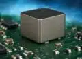
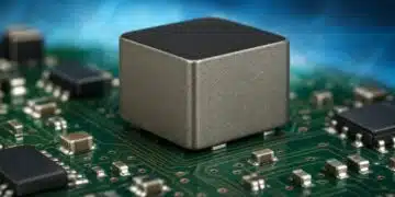
Panasonic commercializes a surface mounted automotive power inductor capable of passing large currents.

Panasonic Corporation announced today that its Industry Company has commercialized a low-loss and high vibration-resistant surface mounted automotive power inductor [1] (PCC-M15A0MF series). This 15.6 mm square inductor meets the market needs for larger working currents and smaller ECU (Electronic Control Unit) board sizes, which are called for with the increasing performance of automotive device functions. The product will be mass-produced starting in January 2022.

RelatedPosts

Panasonic Expands Production of Hybrid Capacitors for AI

Panasonic Industry Extends OS-CON High-Voltage Aluminum Capacitors

Panasonic Extends Polarized Power Relays for Smart Lighting and IoT Applications

As the performance of automotive device functions gets higher, the amount of electric current flowing through electric circuits and the number of ECUs mounted on a vehicle will increase. Therefore, in order to save space inside a vehicle, ECU boards must be downsized. For that purpose, it is essential for electronic components mounted on such boards to be able to pass large currents as well as being small. However, large current type inductors are usually the through hole mounting type and large in size, which means they are unsuitable for miniaturization of the ECU board. Moreover, many passive components such as resistors and capacitors are surface-mounted. As surface mounting cannot be simultaneously performed with through hole mounting, two board processes are required to mount them on the board. Accordingly, Panasonic has commercialized a 15.6 mm square power inductor that can be surface mounted and is capable of passing a large current of 70 A for automotive use (PCC-M15A0MF series), which is an upsized version of the PCC-M1280MF series.

With this highly reliable PCC-M15A0MF series power inductors, the company will improve the reliability of power circuits while contributing to the reduction of environmental impact by saving space in power circuit mounting areas. In the future, the product lineup will also be enhanced by expanding the inductance range of products to respond to market needs.

Features:

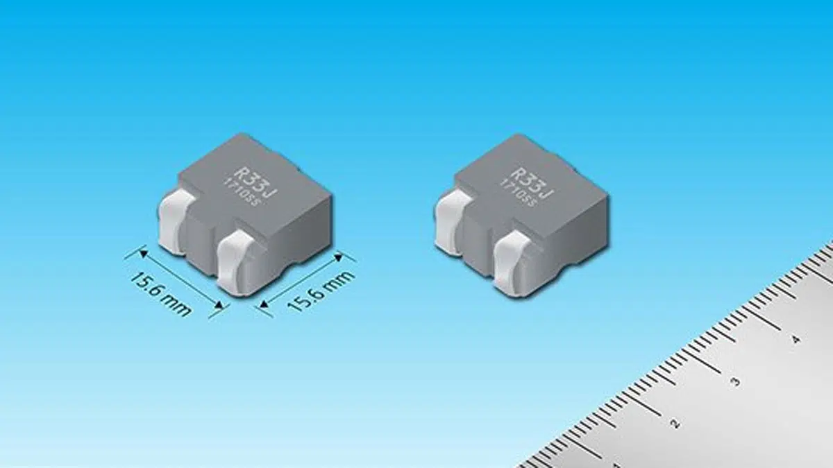
1. Industry’s smallest class (15.6 mm square) of surface-mounted inductor capable of passing large currents*1

  • – Rated current*2: 30 to 70A
  • – Size: Width 15.6 mm x Depth 17.2 mm x Height 10.5 mm

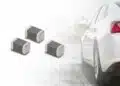
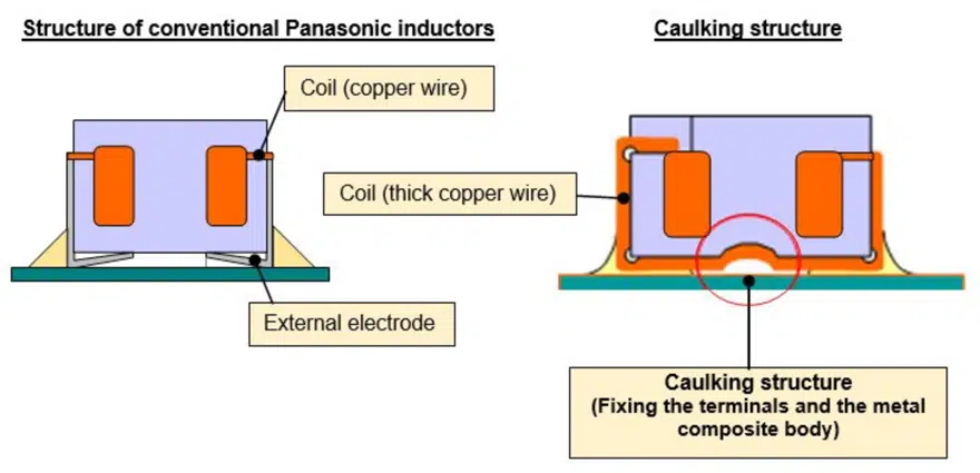
With the rapid electronization of vehicles, the number of ECUs installed inside the engine compartment and directly mounted on engines increases, therefore requiring the downsizing of ECUs. Panasonic adopted metal composite materials [4] using its original metallic magnetic materials and a wound coil using a thick copper wire and further developed a gapless integral structure where the materials and coil are integrally molded without gaps. The new inductor uses a copper wire that is 1.4 times thicker than that of the 12.6 mm square PCC-M1280MF series inductor, reducing the heat generation and loss of the coil. This enabled the new product to pass large currents ranging from 30 A to 70 A despite its small size of 15.6 mm square, which is the industry’s smallest class of surface mounted inductors. These features enabled the direct mounting of ECUs on engines and the space saving of power circuits.

2. The inductor enables ECUs to be directly mounted on engines by achieving excellent heat and vibration resistance.

  • – Heat resistance: 160°C/2000 hours
  • – Vibration resistance: 5 Hz to 2 kHz/30 G

For applications when ECUs are directly mounted on engines, they are required to be able to be installed under severe thermal and vibration conditions. Similarly, coils mounted on ECUs are also required to have excellent heat and vibration resistance. Accordingly, Panasonic achieved high heat resistance up to 160°C by devising the composition of metal composite materials. Moreover, the company adopted its original inductor structure, where both ends of the thick copper wire that makes up the coil are pulled out and used as terminals, and at the same time, a caulking structure is provided on the bottom surface to fix the terminals and the body made of the metal composite materials. This improves vibration resistance after mounting on boards. This structure enables the inductor to be mounted around engines, directly on engines, or near motors.

Comparison of the structure of conventional Panasonic automotive power inductor and the caulking structure; source: Panasonic Industry

3. The environmental impact can be reduced through installation space saving.

  • *1: As surface-mounted inductors as of January 14, 2022 (Panasonic data)
  • *2: Rated current: Current value at which the product temperature increases by 40°C due to self-heating

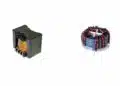
Currently, approximately 60% of automotive power inductors use ferrite [5] as magnetic materials, whereas approximately 40% of those use metal composite materials (Panasonic data as of 2021). By adopting metal composite materials that are suitable for downsizing, the company achieved a smaller inductor size of 15.6 mm square compared to the standard size of 20 mm square for ferrite type inductors with a similar performance. This enables space saving by reducing the installation area by 30 to 50% by replacing ferrite type inductors with a similar performance with the company’s product, thereby enabling the downsizing of devices and the reduction of environmental impact by reducing of the number of components and materials to be used.

Applications:

  • Step-up or step-down DC/DC convertors for gasoline, diesel, and hybrid vehicles [2]
  • High-performance automotive ECU power circuits, automotive ECU circuits with integrated mechanical and electronic components [3]

Basic specifications:

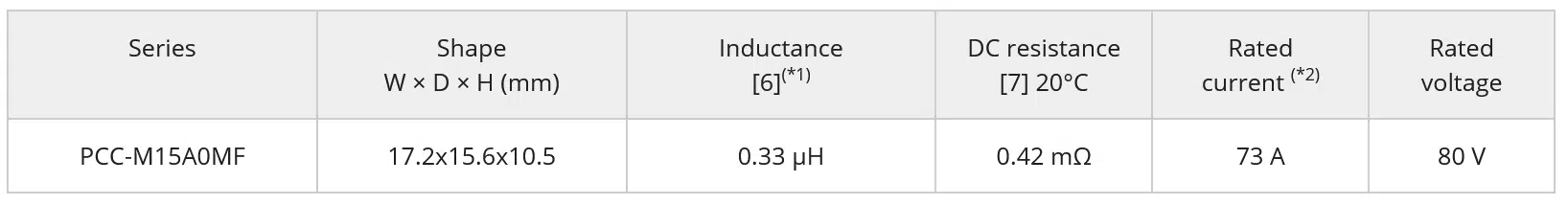
  • *1): Measured at 100 kHz
  • (*2): Current value at which the product temperature increases by 40°C due to self-heating

Term descriptions:

  • [1] Power inductor
    Among inductors, this type is used for electrical circuits in power supply systems and plays a role of a filter to store energy and remove noise in DC/DC converter circuits, etc.
  • [2] DC/DC converter circuit
    This is a circuit that converts direct current from one voltage to another.
  • [3] Integration of mechanical and electronic in-vehicle components
    This refers to a design in which mechanical drive components and automotive ECUs are integrated. Mechanical drive components and automotive ECUs used to be installed separately, but were interconnected via cables. However, the demand for high-precision control, higher degree of freedom in component layout, reduction in the number of cables, etc. has led to the adoption of an integrated configuration of mechanical and electrical components.
  • [4] Metal composite material
    This refers to a magnetic material made by the compression molding of metallic magnetic material-based (iron group) powder insulated with resin.
  • [5] Ferrite
    Magnetic material obtained by mixing and Sintering cobalt, nickel, manganese, etc. with iron oxide as a main component
  • [6] Inductance
    This is an indicator of coil performance. Passing a changing current through a coil will generate a voltage that passes current in a direction that hinders the current change. The rate of the generated voltage is referred to as inductance.
  • [7] DC resistance
    DC resistance is the resistance component of a winding (copper wire). The lower the DC resistance, the smaller the power loss, thereby improving the power supply efficiency.

Related

Source: Panasonic Industry

Recent Posts

Samsung Electro-Mechanics Releases 165C Automotive 0806 Size Power Inductors

21.5.2025
12

Coupled Inductors Circuit Model and Examples of its Applications

21.5.2025
18

Capacitor Ripple Current Testing: A Design Consideration

21.5.2025
31

TDK Releases 0201 High-Frequency Smallest Inductors

20.5.2025
17

Coilcraft Extends Air Core RF Inductors

20.5.2025
9

Bourns Releases Automotive 1W Flyback Transformer

19.5.2025
14

Inductor Resonances and its Impact to EMI

16.5.2025
48

Würth Elektronik Releases High Performance TLVR Coupled Inductors

15.5.2025
34

YAGEO Extends Rectangular Aluminum Electrolytic Capacitor Family

15.5.2025
53

Littelfuse Releases Industry-First SMD Fuse with 1500A Interrupting Rating at 277V

14.5.2025
13

Upcoming Events

May 28
16:00 - 17:00 CEST

Power Over Data Line

View Calendar

Popular Posts

  • Buck Converter Design and Calculation

    0 shares
    Share 0 Tweet 0
  • Boost Converter Design and Calculation

    0 shares
    Share 0 Tweet 0
  • Flyback Converter Design and Calculation

    0 shares
    Share 0 Tweet 0
  • LLC Resonant Converter Design and Calculation

    0 shares
    Share 0 Tweet 0
  • How to Design an Inductor

    0 shares
    Share 0 Tweet 0
  • What is a Dielectric Constant and DF of Plastic Materials?

    4 shares
    Share 4 Tweet 0
  • Capacitor Ripple Current Testing: A Design Consideration

    0 shares
    Share 0 Tweet 0
  • Inductor Resonances and its Impact to EMI

    0 shares
    Share 0 Tweet 0
  • Capacitor Losses (ESR, IMP, DF, Q), Series or Parallel Eq. Circuit ?

    0 shares
    Share 0 Tweet 0
  • Flying Capacitors Explained

    0 shares
    Share 0 Tweet 0

Newsletter Subscription


Passive Components Blog

© EPCI - Leading Passive Components Educational and Information Site

  • Home
  • Privacy Policy
  • EPCI Membership & Advertisement
  • About

No Result
View All Result
  • Home
  • Knowledge Blog
  • Premium Suppliers

© EPCI - Leading Passive Components Educational and Information Site

This website uses cookies. By continuing to use this website you are giving consent to cookies being used. Visit our Privacy and Cookie Policy.
Go to mobile version