


Source: Electronics Specifier article
by Johanson Technology.
For many high power RF applications, the ‘Q factor’ of embedded capacitors is one of the most important characteristics in the design of circuits. This includes products such as cellular/telecomm equipment, MRI coils, plasma generators, lasers and other medical, military and industrial electronics.
Often expressed as a mathematic formula, the Q factor represents the efficiency of a given capacitor in terms of its rate of energy loss. In theory, a ‘perfect’ capacitor would exhibit no loss and discharge a full energy transfer, but in the real world capacitors always exhibit some finite amount of loss.
The higher this energy loss, the more heat is generated within the capacitor that must be dissipated or cooled. For low power applications this heat is insignificant. However, for higher power applications, this heating can be substantial. If the temperature rises significantly, it can damage nearby components and, in extreme cases, de-solder parts from the circuit board.
Although many low power applications do not require consideration of the capacitor’s Q factor, energy losses can increase significantly at higher frequencies leading to other performance issues even in low power circuits. Reduced receiver sensitivity and link budget can sometimes be correlated to higher loss capacitors.
For this reason, high power RF applications typically require High-Q capacitors, which are characterised as having ultra-low equivalent series resistance (ESR). In addition to minimising energy loss, High Q capacitors reduce thermal noise caused by ESR to assist in maintaining desired signal-to-noise ratios.
However, despite its critical role in RF electronics, not all High Q capacitors are created equal. Far from an absolute, it turns out High Q capacitors can be quite relative, varying in performance based on design, manufacturing, quality control and even type of performance testing. Further muddying the water, manufacturers use numerous terms to reference their high-Q capacitors, including: ‘High-Q’, ‘Ultra-High-Q’, ‘Low Loss’, and ‘RF Capacitors’.
“In many ways, ‘High Q’ is a relative term,” said Scott Horton of Johanson Technology, a company that manufactures a variety of multi-layer ceramic High Q capacitors. “It may seem like every capacitor manufacturer has a High Q product, but the performance of the parts in the circuit can be quite different.”
To distinguish between the choices, most MLCC capacitors publish ESR performance values online. However, the performance claims of capacitor manufacturers should be viewed with some uncertainty, said Horton.
Conducted in laboratory settings, ESR tests are most often derived by one of two methods: utilising vector network analysers (VNAs) or resonant lines. However, the accuracy of this data is limited by set-up and calibration of these systems. When measuring capacitor Q on a network analyser, the configuration and calibration are critical to ensure meaningful data is collected. Not all measurements on VNAs are equally valid and in fact poorly calibrated VNAs can yield wildly inaccurate results.
A more reliable method of testing the Q of capacitors is well established Resonant Lines systems. The Boonton 34A resonant line has been the de facto standard in the industry for decades.
Companies like Johanson Technology publish ESR performance data from a Boonton 34A resonant line online. Since this method depends on the frequency accuracy of a signal generator and a very stable resonant line, measurements can be made with extreme precision that is repeatable over time.
“I can’t comment on how some capacitor manufacturers end up with the values they publish, but when I put the capacitor on a resonant line, which is in accordance with the mil standards, and test these parts in a side-by-side A/B comparison test, we see significant differences from their published data. I would believe those relative results,” added Horton.
Consistent manufacturing, layer counts
Another area that can affect the ESR of a High Q capacitor is the quality and consistency of the manufacturing process.
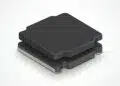
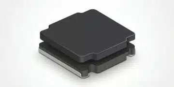
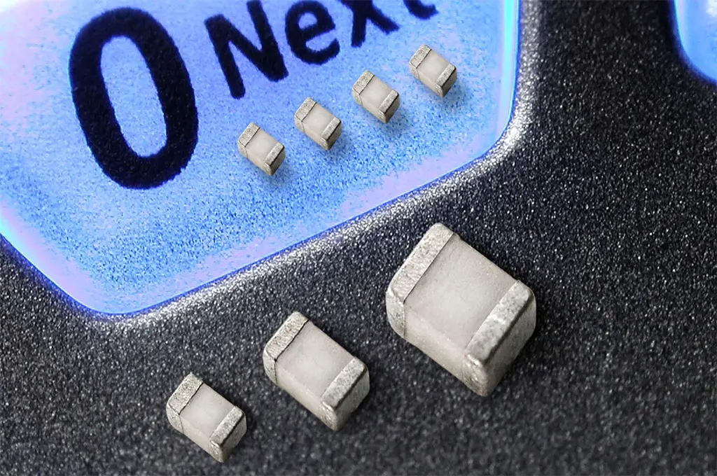
By definition, MLCC capacitors consist of laminated layers of specially formulated, ceramic dielectric materials interspersed with a metal electrode system. The layered formation is then fired at high temperature to produce a sintered and volumetrically efficient capacitance device. A conductive termination barrier system is integrated on the exposed ends of the chip to complete the connection.
In Multi-Layer Ceramic Capacitors (MLCC’s), capacitance is primarily determined by three factors: the k of the ceramic material, the thickness of the dielectric layers, and the overlap area and the number of the electrodes. So a capacitor with a given dielectric constant can have more layers and wider spacing between electrodes, or fewer layers and closer spacing to achieve the same capacitance.
Significantly changing the layer counts in MLC capacitors can change performance characteristics significantly. As such, the leading capacitor suppliers tightly control the layer counts of each part made. Unfortunately, this is not a ‘given’ in the industry with some suppliers delivering products with the same part number, but a variable number of layers. In short, the same part number can have significantly different designs which lead to undesirable impedance changes in the capacitor. Within a supplier and more importantly from supplier to supplier.
“If a MLCC manufacturer is not tightly controlling the layer count, they might be providing 10 layer parts in one batch and then later deliver 17 layer parts in a subsequent batch,” explained Horton. These two parts will not perform the same at high frequencies.
Another cause of performance variation occurs when OEMs purchase through resellers who buy from multiple factories. In this scenario, the different factories have different designs which have different high frequency performance. Thus, the items are sourced from different manufacturers which can produce significant variation in high frequency performance. This, too, can lead to a very real scenario where parts are not consistent which result in system performance variation.
The Series Resonant Frequency or SRF is a key performance metric affected by varying layer counts. This variation can negatively affect the performance of any LC RF filters where those capacitors are used. Bandpass filters, for example, often utilise the resonant frequencies of the capacitor to ‘shape’ its performance.
This means that when layer counts vary, filters may not perform as designed and allow radiated emissions to exceed the FCC or ETSI requirement in the finished product. Lot to lot changes in capacitor performance can lead to costly product recalls.
“If there is a shift in the series resonance frequency, your filter may no longer meet FCC emission requirements,” said Horton. “So, by tightly controlling the layer counts, manufacturers help ensure that LC filter performance remains consistent from lot to lot, day to day, month to month, year to year.”
High loss capacitors can impact aspects such as battery life, as well. For systems in which RF amplifiers are utilised, it is inefficient to have power absorbed or dissipated by a capacitor. Engineers must then use amplifiers to make up for losses caused by low Q capacitors which results in faster battery drain in handheld devices.
High Q capacitors can also improve receiver sensitivity by reducing losses between the antenna and the transceiver.
Variance in capacitor design, construction
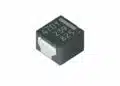
High-Q capacitors vary from standard capacitors in design. To achieve the lowest losses, leading companies such as Johanson Technology utilise the lowest loss dielectrics, inks and electrode options.
For example, most low cost commodity capacitors utilise nickel electrodes. However, nickel is a poor conductor known for high loss at RF and microwave frequencies.
Silver and Copper electrodes are superior and perform better than nickel and are used for most High Q applications. This type of electrode has the added advantage that it does not create a magnetic field like nickel. This is important factor for applications such as MRI receiver coils where strong magnetic fields are involved.
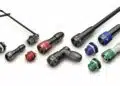
For the highest power RF applications, a number of leading manufacturers offer pure palladium electrodes. However, silver is a superior conductor when compared to palladium at higher frequencies. For this reason, Johanson Technology incorporates silver electrodes in its ultra- High Q (lowest ESR loss) offering, the E-Series multilayer RF capacitors in their high power standard 1111, 2525 and 3838 size capacitors.
Capacitors in vertical orientation
Even minor details like the orientation of the capacitor in the tape reels can have a direct impact on the performance of a circuit.
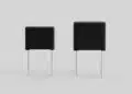
Traditionally, High Q capacitors are available primarily in a horizontal electrode configuration when mounted in tape and reels. Now, some leading manufacturers such as Johanson Technology are offering the MLCC capacitors in both horizontal and vertical electrode orientation configurations.
However, mounting capacitors in a vertical configuration is also an industry ‘trick’ that effectively extends the usable frequency range of capacitors.
In addition to the SRF (which is based on the given physical size/construction and a given capacitance value), capacitors also exhibit parallel resonant frequencies (PRF). As a rule of thumb, PRF is approximately double the SRF.
At the PRF, the transmission impedance goes relatively high, and the capacitor is very high loss around this frequency.
By mounting the capacitor in a vertical position instead, the odd PRFs are eliminated. This pushes the first PRF significantly higher in frequency which allows the capacitor to be used at significantly higher frequencies.
High Q relativity
If there is a lesson from this discussion of High Q capacitors, it is that selecting the ideal MLC capacitor requires more than a voltage, capacitance value and tolerance. This may also explain why a capacitance value from one supplier may not be a one to one correspondence with another supplier in critical matching circuits. The design and quality/consistency of manufacturing plays just as big a role, as does the type of testing to verify performance.
“Don’t assume that because the capacitor is labelled ‘High Q’ it is going to deliver the required performance,” concluded Horton. “These capacitors play a critical role in RF transmission and reception of military, medical and industrial electronics, so they must perform as expected, optimised to minimise energy loss and variation from one batch to another. If not, these electronics may not perform as expected in the field.”