AVX Corporation released a technical paper written by Ron Demcko and Ashley Stanziola on general introduction to conductive adhesives. It aims to assist end-users in the conductive epoxy attachment of SMT (Surface Mount Technology) components.
Abstract
Compared to the vast majority, capacitor attachment via conductive epoxy is not a common technique among end-user applications. A significant amount of growth in capacitor usage has occurred in solder attachment methods. Furthermore, many publications on attachment methods focus predominantly on optimizing the multiple methods of solder component attachment. Therefore, confusion exists on the requirements needed to ensure reliable long-term attachment when using conductive epoxy material systems.This paper serves as a general introduction to conductive adhesives. It aims to assist end-users in the conductive epoxy attachment of SMT (Surface Mount Technology) components.
Introduction
Conductive Epoxy Attachment Basics
Conductive Epoxy attachment is an alternative attachment method of soldering. As the name indicates, a conductive glue replaces solder during the attachment of a device to a PCB (Printed Circuit Board). Devices attached can range from passive components, and semiconductor die to EMI (Electromagnetic Interference) gaskets. Conductive epoxies are created using high electrically conductive metals. Silver is commonly used, but other options include nickel, copper, palladium, or gold. The conductive particles are mixed and distributed throughout a 1- or 2-part epoxy or silicone. The resulting epoxy is dispensed onto the components SMT pads commonly via a pneumatic needle. Components are placed on the epoxy-coated pads, and the assembly is cured for a specified time and temperature. There are alternate curing conditions such as UV (Ultraviolet) light. The simplified concept of the technology is that when the epoxy carrier cures, its volume shrinks, and that causes the metal particles to make contact. The contact between the metal particles creates a conduction path.
The epoxy attachment might seem straightforward. However, realistically, the composition, selection, and use of the many conductive epoxy families is anything but straightforward.
Why Conductive Epoxy
For decades electrically conductive epoxies have been used as an assembly method in applications such as microelectronics, lead frames, and hybrid microcircuits. Nonetheless, conductive epoxy attachment is not general knowledge, and questions still arise. The frequently asked questions are, “why use epoxy attachment, given that there are limited suppliers for conductive epoxy?” and “what are the components compatible for this attachment method”?
Even though most end-users know little, to none, about conductive epoxy attachment, its use is well known and documented inside a very narrow section in the electronics industry. As reported by Li and Morris1, conductive epoxies offer several advantages over solder. Conductive epoxy’s primary advantage is a more environmentally friendly attachment than the SnPb soldering process. That primary advantage has diminished due to the introduction of lead-free solder (Sn solder). However, what is still significantly apparent is that epoxy attachment is a much simpler attachment process. Also, the process is much less capital intensive compared to solder attachment processes.
In addition, a significant advantage is that conductive epoxy attachment exposes components to very low levels of thermal-induced stress during the process. End-systems that use conductive epoxy have the inherent advantage of all components having compliant connections to the substrate. This results in enhanced performance across the shock, vibration, thermal cycling, and mechanically induced strain.
A disadvantage of lead-free solder is that it is commonly less elastic compared to lead-based solders. Therefore, lead-free solder systems have the potential to develop “micro-cracking.” The use of conductive epoxy will eliminate solder micro-cracking concerns.
The selection of a specific conductive epoxy is not simple. At a minimum, epoxy types can be one-part, two-part, or silicone-based. Whichever option is chosen for the “carrier” material, its purpose is to suspend the conductive metal particle in the carrier fluid until they are dispensed and cured.
One-part epoxy is advantageous in eliminating the need to be mixed before use. Typically, one-part epoxy families must be refrigerated before use and cure at relatively high temperatures (in the order of 150°C).
Two-part epoxies often cure at temperatures as low as room temperature and eliminate the need for cold storage. However, two-part systems have a short working time before curing, and they require great care when mixing the parts to ensure proper ratios.
Careful analysis of epoxy must occur since the carrier type dramatically affects the lead attachment, integrity, and systems performance. End-users must choose epoxies based upon electrical, ease of processing, and physical and reliability requirements, such as resistivity, shear adhesion, impact resistance, and environmental performance specifications. Typical minimum acceptable requirements are a volume resistivity no more significant than one milliohm-centimeter (mΩ-cm), less than 20% shift in contact resistance after 500 hours at 85°C, 85% relative humidity (RH), and adequate impact resistance2.
From a reliability point of view, epoxies age and have increased resistance with time. They also have unstable moisture performance and varying environmental performance such as life, 85/85, shock testing, and high-temperature exposure capability. The unstable moisture performance and varying environmental performance can potentially be a very limiting negative feature of conductive epoxies.
Process and assembly concerns range from increased difficulty of dispensing, rework, air entrapment in the epoxy, less self-alignment from fine pitch components, and much lower heat conduction than solder based terminations. Vertical pneumatic dispensers commonly solve the difficulty of dispensing3.
Though the list of added concerns appears significant, most of these concerns diminish when conductive epoxy is used in hybrid micro-circuits with ceramic packages and hermetically sealed to have controlled atmospheres.
SMT Components and Conductive Epoxies
When selecting SMT components, extreme care must be exercised in conductive epoxy applications since not all SMT component terminations are compatible with conductive epoxy attachment. Terminations compatible with conductive epoxy consist of Ti/W/Au, Ti/W/Ni, AgPd, CuAu, NiAu, ENIG, and ENEPIG.
RoHS accepted Sn and SnPb terminated SMT devices are not compatible with conductive epoxy attachment since conductive epoxies absorb water. The absorption would cause the Sn Plated layer on an SMT device to oxidize. As the oxidation increases, the SMT devices’ contact resistance and heating losses relative to the substrate increase. Furthermore, microcracks can occur on Sn terminated parts when used in conductive epoxy systems. These cracks reduce the shear strength of the SMT part to the mounting pads.
SMT technology is evolving so rapidly within the passive component world that a review of recent significant trends and developments is necessary.
Three main areas should be focused on relative to the conductive epoxy topic:
1) Component miniaturization and new termination configurations
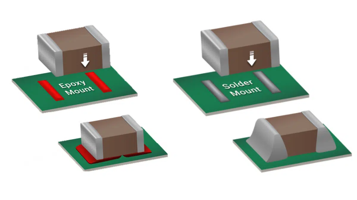
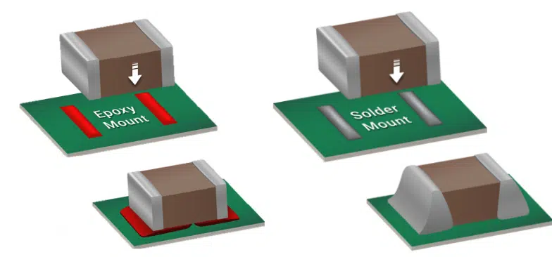
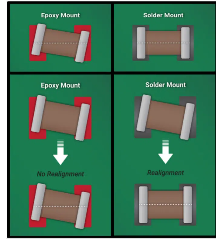
The introduction of miniature case sizes, 0201 and 01005 MLCCs (Multilayer Ceramic Capacitor), and complex high-density terminations, such as eight terminal 0306s, introduce increased processing concerns when using conductive epoxy. A disadvantage of conductive epoxy vs. solder is that components do not self-align in conductive epoxy as they do in solder processes. Thus, placing small case size components must be handled with extreme care to ensure exact alignment on mounting pads. Another concern comes from the fact that conductive epoxies cure without moving and flowing. As the epoxy flow stops, the epoxy exhibits a “thinning tail” characteristic. Flow control and dispensing needle orientation is essential since excess epoxy can easily bridge the terminations once the components are placed, and the bridge will create a short. Therefore, conductive epoxy must be applied with great accuracy and flow control. In figures 1.1 & 1.2, an example of alignment and excess conductive epoxy is shown.
2) New termination material sets
As stated previously, conductive epoxies provide a compliant termination, advantageous for SMT devices surviving shock, vibration, thermal cycling, and substrate-induced strain.
FlexiTerm is a material system invented to eliminate cracking of MLCCs due to strain from temperature cycling, depanelization or shock/vibration, and bending. Flexiterm essentially negates the compliant advantage of conductive epoxy attachment.
FlexiTerm® and FlexiSafe™ are series that have a compliant termination compatible with SnPb and SnPb free solder processes. The key to FlexiTerms performance is a “conductive epoxy” placed under the final metal termination finish.
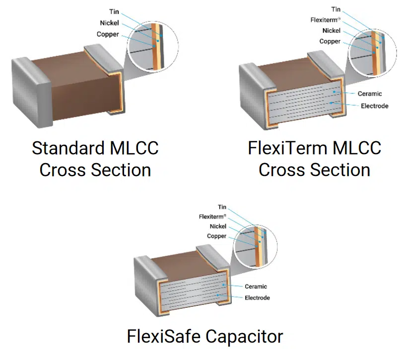
The conductive epoxy forms a compliant cushion inside the SMT devices termination structure. The cushion works as a “Shock absorber,” preventing internal cracking4. End-users sometimes confuse “epoxy termination” with “epoxy lead attachment.” The conductive epoxy used in FlexiTerm® & FlexiSafe™ terminations is not the same material used in the conductive epoxy lead attachment. Therefore, End-users should not confuse the two. See figure 2 for termination cross-section of FlexiTerm® and FlexiSafe™ Devices.
The use of FlexiTerm technology is accepted within MIL PRF 32535, NASA (The National Aeronautics and Space Administration), and ESA (European Space Agency) specifications. FlexiTerm & FlexiSafe capacitors do not exhibit increased Equivalent Series Resistance (ESR) or ESR instability over time, moisture, or temperature.
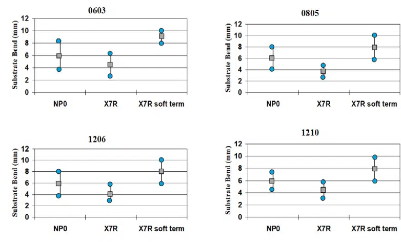
The Strain/PCB deflection performance of FlexiTerm technology is shown on a case size & dielectric basis to standard SMT capacitors in figure 3. FlexiTerm Capacitors are not compatible with conductive epoxy attachment material systems.
3) New SMT device technologies – Multi-Layer Organic devices (MLO)
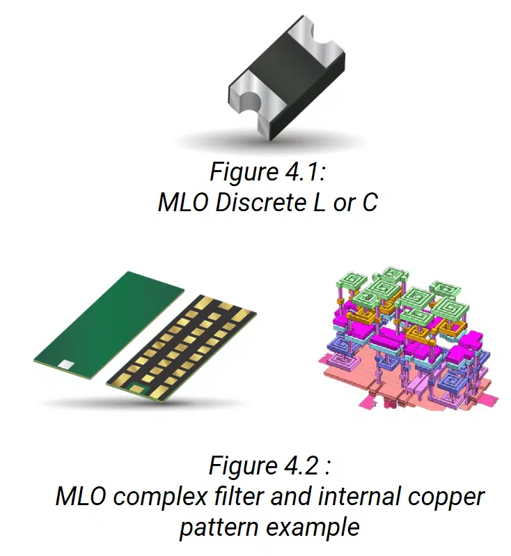
MLO technology is essentially a 3D micro-stack of low loss dielectrics with laser direct imaged copper traces that form inductors and capacitors. These inductors and capacitors are typically very high Q and very tight tolerance. The inductors and capacitors can take the form of small case size, low profile height discrete SMT packages with castellated terminations (0402, 0603), or they can take the form of larger RF modules.
Modules are formed by the individual capacitor and inductor layers being stacked vertically. Options for vertical stack connect are copper-based vias and blind vias. The resulting 3D stack can form potentially very complex RF filters in small thin packages – see figure 4.
MLO components can be a viable alternative to Low-Temperature Co-fired Ceramic (LTCC) since they are inherently low loss (because of thick copper traces and low loss dielectrics), much smaller physical sizes, and similar Coefficient of Thermal Expansion (CTE) to most substrates. MLO structures can potentially have a high pinout count – whether for signals or heat conduction.
MLO Termination options for discrete MLO capacitors and inductors are not compatible with conductive epoxy since they are Sn-based.
However, the complex filters have two conductive epoxy compatible terminations – NiAu, and ENEPIG. ENEPIG is short for Electroless Nickel Electroless Palladium Immersion Gold.
Both NiAi and ENEPIG are compatible with conductive epoxy and will eliminate the oxidation problem that copper termination exhibit when they are in the air. Without ENEPIG singular material copper, only termination pads would oxidize and introduce both poor solderability and reduced electrical connection integrity.
Summary
SMT components used in conductive epoxy processes must be compatible with the hydroscopic nature of electrically conductive epoxies. Conductive epoxy attachment offers a very low stress, low-temperature attachment method of creating end circuitry.
Several important trends in SMT component technology are emerging, possibly limiting (small case size, FlexiTerm termination) – or expand (MLO technology) using conductive epoxy as an attachment method.
References
- 1 Li, Morris, An Introduction To Electrically Conductive Adhesives, International Journal of Microelectronic Packaging 1998
- 2 D. J. Small, Reliability Considerations of Electrically Conductive Adhesives, Loctite Corporation Technical Paper, www.loctite.com
- 3 Salisbury, Thermal Management of Surface Mounted Tantalum Capacitors, www.AVX.com
- 4 Demcko, Lennox, Flexisafe™ MLCC Termination Performance, www.AVX.com