Passive Components Blog
No Result
View All Result
  • Home
  • NewsFilter
    • All
    • Aerospace & Defence
    • Antenna
    • Applications
    • Automotive
    • Capacitors
    • Circuit Protection Devices
    • electro-mechanical news
    • Filters
    • Fuses
    • Inductors
    • Industrial
    • Integrated Passives
    • inter-connect news
    • Market & Supply Chain
    • Market Insights
    • Medical
    • Modelling and Simulation
    • New Materials & Supply
    • New Technologies
    • Non-linear Passives
    • Oscillators
    • Passive Sensors News
    • Resistors
    • RF & Microwave
    • Telecommunication
    • Weekly Digest

    Inductor Resonances and its Impact to EMI

    Developing Low Inductance Film Capacitor using Bode 100 Analyzer

    Highly Reliable Flex Rigid PCBs, Würth Elektronik Webinar

    Würth Elektronik Releases High Performance TLVR Coupled Inductors

    YAGEO Extends Rectangular Aluminum Electrolytic Capacitor Family

    Dr. Tomas Zednicek Vision for Europe 2025 Passive Electronics Market

    Littelfuse Releases Industry-First SMD Fuse with 1500A Interrupting Rating at 277V

    TDK Unveils Industry Highest Rated Current Multilayer Chip Beads

    Vishay Releases Automotive SMD Thick Film Power Resistor for Enhanced Protection Against Short Transient Pulses

    Trending Tags

    • Ripple Current
    • RF
    • Leakage Current
    • Tantalum vs Ceramic
    • Snubber
    • Low ESR
    • Feedthrough
    • Derating
    • Dielectric Constant
    • New Products
    • Market Reports
  • VideoFilter
    • All
    • Antenna videos
    • Capacitor videos
    • Circuit Protection Video
    • Filter videos
    • Fuse videos
    • Inductor videos
    • Inter-Connect Video
    • Non-linear passives videos
    • Oscillator videos
    • Passive sensors videos
    • Resistor videos

    Inductor Resonances and its Impact to EMI

    Highly Reliable Flex Rigid PCBs, Würth Elektronik Webinar

    Causes of Oscillations in Flyback Converters

    How to design a 60W Flyback Transformer

    Modeling and Simulation of Leakage Inductance

    Power Inductor Considerations for AI High Power Computing – Vishay Video

    Coupled Inductors in Multiphase Boost Converters

    VPG Demonstrates Precision Resistor in Cryogenic Conditions

    Comparison Testing of Chip Resistor Technologies Under High Vibration

    Trending Tags

    • Capacitors explained
    • Inductors explained
    • Resistors explained
    • Filters explained
    • Application Video Guidelines
    • EMC
    • New Products
    • Ripple Current
    • Simulation
    • Tantalum vs Ceramic
  • Knowledge Blog
  • Suppliers
    • Who is Who
  • Events
No Result
View All Result
Passive Components Blog
No Result
View All Result

DC-DC Output Smoothing Using Ultra-High CV Aluminum Electrolytic Capacitors; Kemet App Note

23.11.2020
Reading Time: 6 mins read
A A

Many electronic designs today contain subsystems, such as DC-DC converters and linear voltage regulators, that require very large bulk capacitance at specific nodes.  Electrolytic capacitors (also called e-caps, electrolytics, or even just lytics) are a natural choice to fit this requirement, but they often fall short due to their relatively high series resistance and poor reliability performance.  To fill this gap, more exotic devices have been developed, but they can be prohibitive because of cost.  Recent advances in materials and construction technology has resulted in a new class of aluminum e-caps to solve this issue.  They provide extremely high capacitance per volume density and performance characteristics that meet strict automotive standards while maintaining a competitive price point.

Electrolytic Capacitors

Figure1: Basic Electrolytic Capacitor Structure
Figure 1: Basic Electrolytic Capacitor Structure

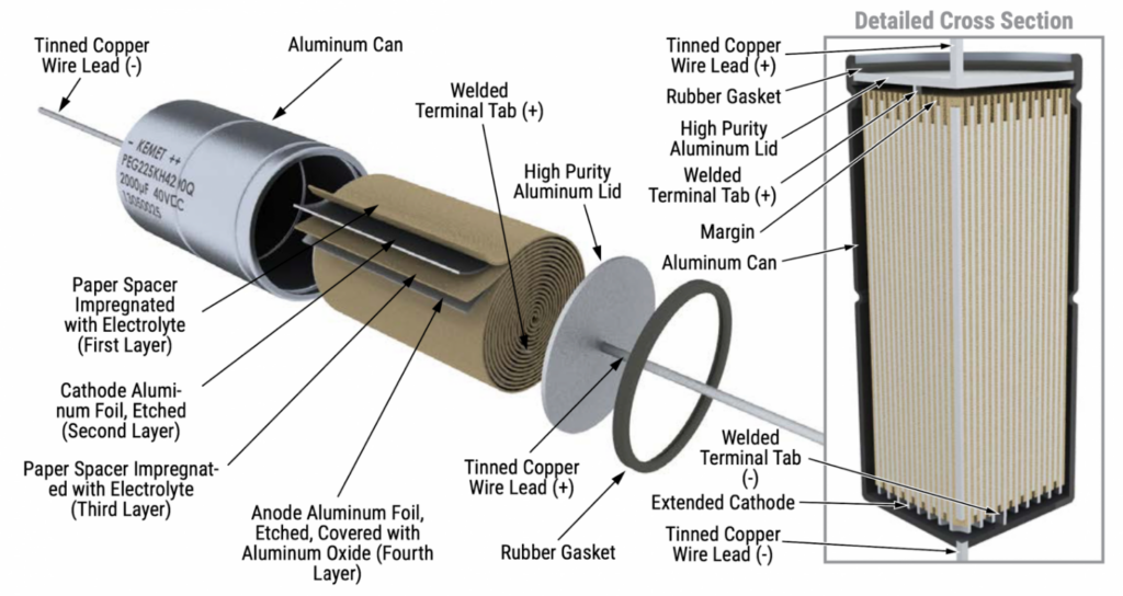
The development of the electrolytic capacitor has been one of the main factors in the successful miniaturization and increased performance of every variety of electronics used today.  The basic e-cap construction is shown in the figure below.

RelatedPosts

Inductor Resonances and its Impact to EMI

Developing Low Inductance Film Capacitor using Bode 100 Analyzer

Highly Reliable Flex Rigid PCBs, Würth Elektronik Webinar

Since capacitance is a function of surface area, aluminum foils are first etched to create a rough contour with maximal contact area.  Capacitance is also an inverse function of dielectric thickness, as shown in the equation below.

C = εA/d

Where ε is the permittivity of the dielectric, A is the area of the anode and cathode, and d is the physical distance separating the two (also the thickness of the dielectric.)

To realize the thinnest possible dielectric while still following the aluminum contours, an oxide layer is grown on the anode foil surface.  Oxides act as a unidirectional dielectric, only blocking the flow of current in one direction.  This leads to the well-known polarization of e-caps, as a reverse voltage will actively remove the oxide layer.

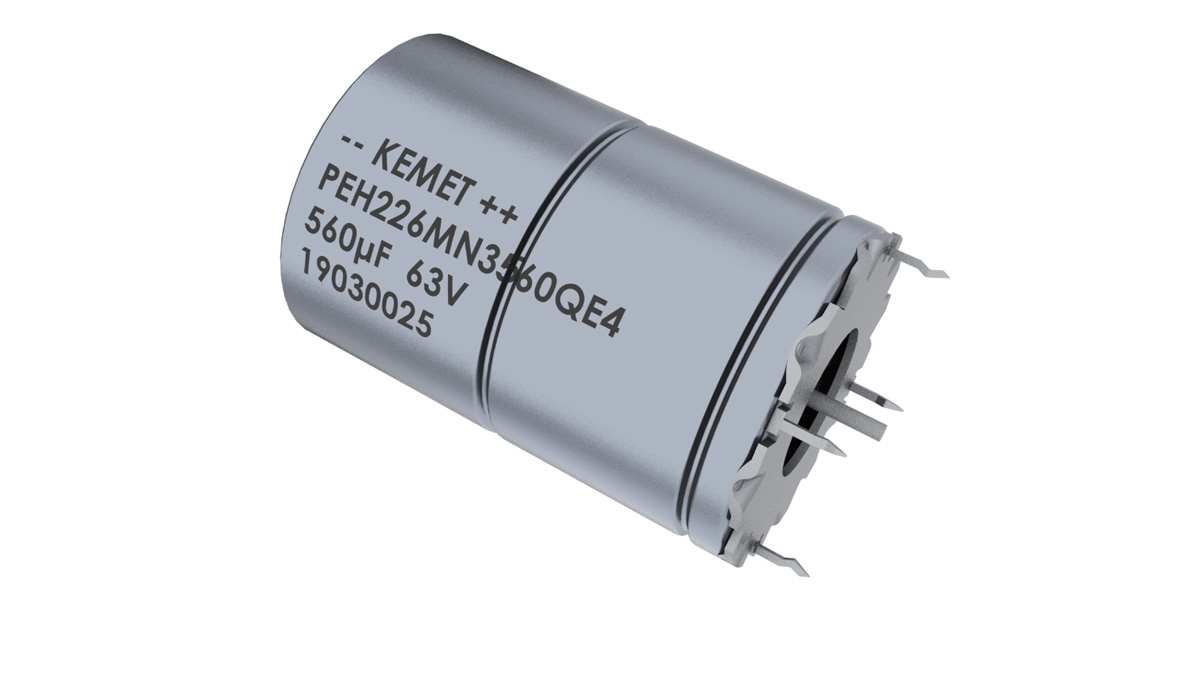
Since the anode is roughly contoured, it is difficult to make electrical contact with the oxide layer for the second plate of the capacitor.  This is where the electrolyte comes into play.  Traditionally a “wet” liquid, the electrolyte fills in the peaks and valleys of the anode-oxide surface, and effectively creates the cathode.  To produce a good terminal contact with this electrolyte, a second foil layer and a paper separator are added to fully complete the capacitor structure.  This aluminum-electrolyte-paper sandwich is then rolled or “wound” into a can and sealed with two terminals to finish the final device.  As shown below, an aluminum can and lid welded to two leads can be used to create an axial device formfactor.

Figure 2: Axial Electrolytic Capacitor Construction

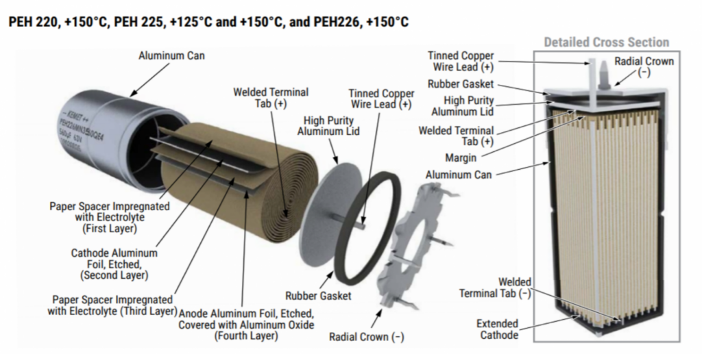
Alternately, the can contact can be made using a “crown” to create a radial device that stands up vertically, as shown in the figure below.

Figure 3: Radial Electrolytic Capacitor Construction

KEMET’s Ultra-High CV Line

The new generation of high performance e-caps by KEMET has been designed for automotive applications with extremely high demands. Low ESR is the result of a low resistive electrolyte/paper system and an all-welded design. The winding is housed in a cylindrical aluminum can with a high purity aluminum lid and a high quality rubber gasket. Thanks to its mechanical robustness, this series is suitable for use in mobile and aircraft installations, with operation up to +150°C. KEMET’s automotive grade capacitors meet the demanding Automotive Electronics Council’s AEC–Q200 qualification requirements and offer:

  • 2,000 hours at +150°C
  • Ultra-High CV
  • Extremely high ripple current
  • Up to 27 ARMS ripple current, continuous load
  • ESR stability over lifetime
  • High vibration resistance
  • Polarized all-welded design
  • Outstanding electrical performance

The axial and radial crown form factors are shown in the figures below:

Figure 4: Radial Crown form factor of KEMET’s ultra-high CV capacitor
Figure 5: Axial form factor of KEMET’s ultra-high CV capacitor

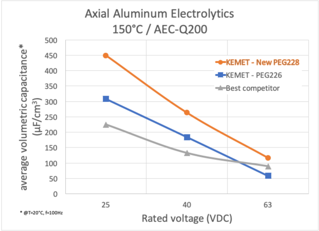
These devices offer industry-leading volumetric capacitance, resulting in significant size improvements across the entire voltage range when compared to the next best competitor.  This trend is shown in the following figure, where the capacitance at 25V is nearly double the best competitor.

Figure 6: Volumetric capacitance comparison for difference voltage ratings

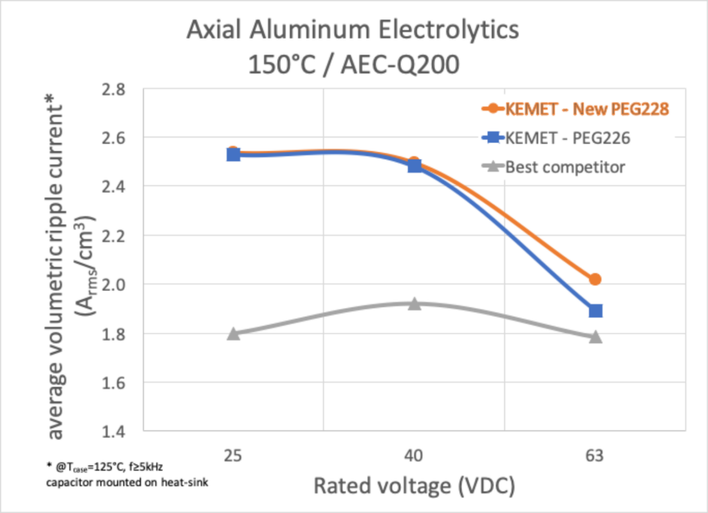
In addition to small size, the ultra-high CV devices boast extremely low series resistance values and can tolerate high ripple currents even at high temperature.  The comparison in ripple current to the best competitor at 150 ℃ is shown below.

Figure 7: Ripple current comparison at different voltage ratings

Voltage Regulator Output Smoothing

In nearly every electronic circuit, some sort of voltage regulating system is required.  The most basic of these is the linear dropout regulator, or LDO, where the output voltage is realized by passing the output current through a controlled variable resistor (often a MOSFET.)  The feedback control to hold the output voltage steady has an associated time constant, and often cannot respond quickly to sudden or intense changes in load current.  To create a constant output voltage during these lags in regulation response, an output smoothing capacitor is often employed to supply current during transient events.  Shown in the figure below, the LDO depends on the 2,200 uF capacitor for maintaining a consistent five volt output.

Figure 8: Example of LDO output smoothing (“PLDuino”)

Figure 8: Example of LDO output smoothing (“PLDuino”)

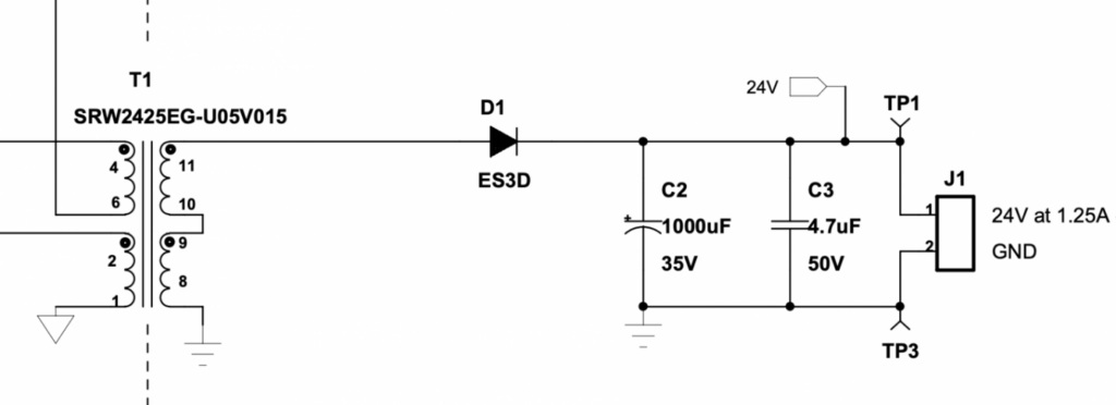
In contrast to LDOs, switching converters regulate output voltage using the electromagnetic energy storage properties of inductors and capacitors.  By controlling the switching duty cycle, a fixed output voltage can be maintained by adjusting to the varying load current.  Just as in the LDO example, this control mechanism has an associated time constant that prevents switching regulators from responding quickly to intense load current transients.  As such, output smoothing capacitors can be used to supply the load while the duty cycle is tuned to the appropriate value.  An example of the output stage of a flyback converter is shown in the figure below where a 1000 µF electrolytic is used as an output smoothing device.

Figure 9: Example of DC-DC Output Smoothing (“TI Highline Flyback”)

In both the linear and switching topology, the output smoothing capacitor is typically quite large to minimize voltage drop during discharge into the load and compensate for inductor ripple current.  Electrolytic capacitors are often an ideal choice for these components due to their high volumetric capacitance and low cost.  In addition, their polarization requirements fit nicely with the constant output voltage of converter applications.

Related

Source: Kemet

Recent Posts

Inductor Resonances and its Impact to EMI

16.5.2025
15

Developing Low Inductance Film Capacitor using Bode 100 Analyzer

15.5.2025
27

Highly Reliable Flex Rigid PCBs, Würth Elektronik Webinar

15.5.2025
14

Würth Elektronik Releases High Performance TLVR Coupled Inductors

15.5.2025
15

Causes of Oscillations in Flyback Converters

15.5.2025
9

YAGEO Extends Rectangular Aluminum Electrolytic Capacitor Family

15.5.2025
28

Dr. Tomas Zednicek Vision for Europe 2025 Passive Electronics Market

14.5.2025
29

Littelfuse Releases Industry-First SMD Fuse with 1500A Interrupting Rating at 277V

14.5.2025
7

TDK Unveils Industry Highest Rated Current Multilayer Chip Beads

14.5.2025
17

Vishay Releases Automotive SMD Thick Film Power Resistor for Enhanced Protection Against Short Transient Pulses

14.5.2025
8

Upcoming Events

May 28
16:00 - 17:00 CEST

Power Over Data Line

View Calendar

Popular Posts

  • Boost Converter Design and Calculation

    0 shares
    Share 0 Tweet 0
  • Buck Converter Design and Calculation

    0 shares
    Share 0 Tweet 0
  • Flyback Converter Design and Calculation

    0 shares
    Share 0 Tweet 0
  • Inductor Resonances and its Impact to EMI

    0 shares
    Share 0 Tweet 0
  • LLC Resonant Converter Design and Calculation

    0 shares
    Share 0 Tweet 0
  • SEPIC Converter Design and Calculation

    0 shares
    Share 0 Tweet 0
  • MLCC Case Sizes Standards Explained

    0 shares
    Share 0 Tweet 0
  • What is a Dielectric Constant and DF of Plastic Materials?

    4 shares
    Share 4 Tweet 0
  • DC-DC Converter Basic Characteristics and Formulas

    0 shares
    Share 0 Tweet 0
  • Dual Active Bridge (DAB) Topology Explained

    0 shares
    Share 0 Tweet 0

Newsletter Subscription


Passive Components Blog

© EPCI - Leading Passive Components Educational and Information Site

  • Home
  • Privacy Policy
  • EPCI Membership & Advertisement
  • About

No Result
View All Result
  • Home
  • Knowledge Blog
  • Premium Suppliers

© EPCI - Leading Passive Components Educational and Information Site

This website uses cookies. By continuing to use this website you are giving consent to cookies being used. Visit our Privacy and Cookie Policy.
Go to mobile version