


Source: EE Power article
by George Slama at Würth Elektronik eiSos
Engineers are under time and budget pressures to complete their tasks efficiently. Designing a power supply can be a daunting task, especially for those without much experience. One of the most critical components will be magnetic. For a basic non-isolated buck, boost, or SEPIC converters, the power storage inductor must be determined.
There are many possibilities for the output filter, which consists of the inductor and capacitor. With higher inductance, the capacitor can be smaller and vice versa. Physical size and cost are often considerations that dictate biasing the design one way or the other. Designing your own customer inductor may seem like a good idea at first. After all, you’ll get exactly what you want. But will you?
Consider the time and effort that first go into some type of design, and then into procuring the necessary cores, bobbins, wire and later into actually winding and gapping the core. This also requires equipment since only the simplest inductors can be made by hand. The best performing inductors generally use winding techniques (rectangular wire wound on edge) and materials (pressed composites) not available outside of manufacturing facilities.
Standardizing Magnetic Components
The next choice is to use simulation software. Using 3D finite element software will give the best results because it can better account for ac losses resulting from winding geometry, as opposed to 2D or purely numeric calculations. In either case, time is needed to create the models or to simply enter and run the various proposed inductor values.
If one is just beginning to learn the process of power supply design, then there is a benefit in understanding the seemingly infinite number of choices available with regard to all components, not just magnetic and their effect on the design. No one suggests there is only one unique combination of resistors and capacitors that makes control loop compensation work. Likewise, with magnetic components, there is no one unique solution. The multitude of design requirements is balanced against each other to arrive at the best solution for each situation.
It is interesting that in power supplies the magnetic components are the only ones where engineers feel they must design their own. Why is this? Nobody designs and builds their own MOSFETs, diodes, capacitors, resistors or controllers. Why the magnetics? Are magnetic components (inductors and transformers) the last frontier to be standardized. Hardly so. The reality is simple. The magnetic components are one of the last freedoms the engineer has where he can make adjustments to compensate or optimize the circuit. This is especially true for transformers, less so for inductors.
Standard low power inductors come in standard values just like resistors and capacitors. Equally, there are many different types and styles that cover a broad range of applications. It might be possible for one company to make all possible parts eliminating the need for custom inductors. Obviously, we can all think of cases where this is not true. There will always be special or unique requirements and situations that can only be fitted with a custom inductor. However, in the vast majority of cases a standard inductor, carefully chosen from the thousands available will be the fastest and most cost-effective solution without any compromise.
Choosing the Best Inductors
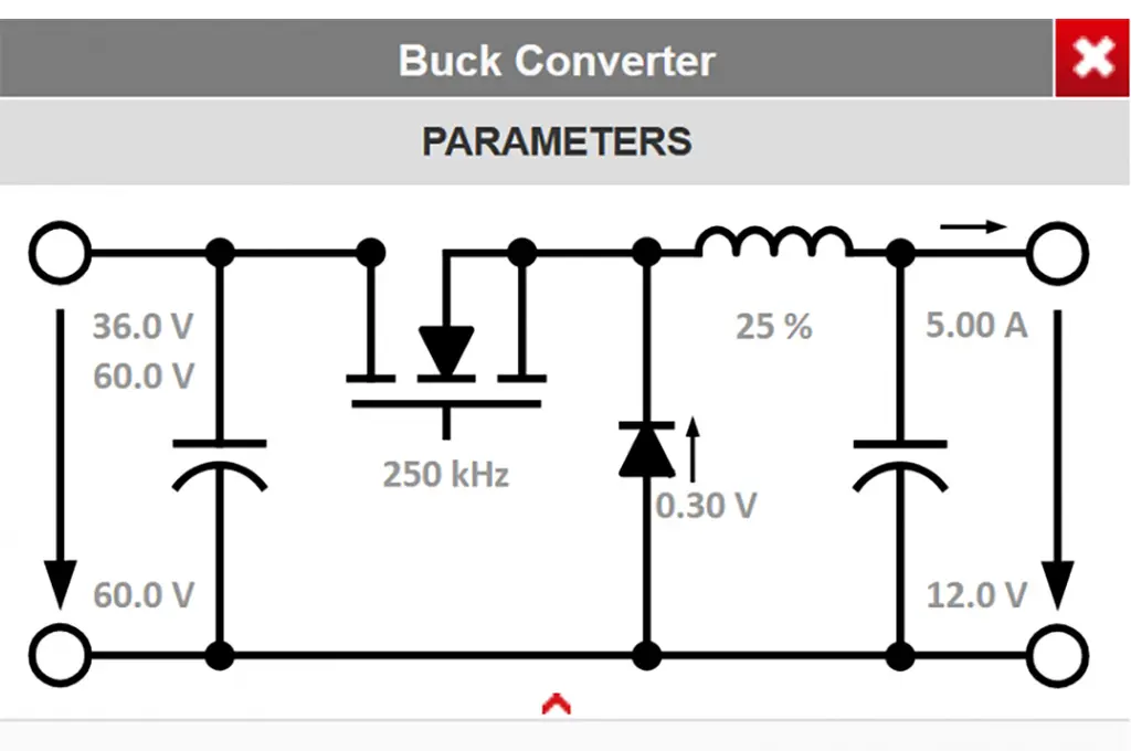
Würth Elektronik eiSos, as a manufacturer of standard inductors, has a free online tool to help engineers analyze and quickly select the best inductor for their application. No need to acquire cores, bobbins, wire, winding, and equipment or invest time in experimentation and guesswork. With REDEXPERT, the engineer simply inputs his topology with basic parameters and the tool instantly lists all suitable inductors conveniently in one table.

Figure 1: Setting up the Parameters for a Buck Converter
No need to enter information for each possibility and re-run the simulation as in traditional software. From the list, one can narrow the selection based on requirements such as height, volume, losses, temperature rise, performance, and margin. The loss data can be reviewed which includes all core and winding losses, both dc and ac. It is important to note here that all losses due to the winding structure are included. This is simply not possible in a simulation program unless done in FEM with a detailed 3D drawing, a time-consuming process in itself, and knowledge of the material properties.
The data is highly accurate, more so than any modeling or simulation software because it is taken from actual measurements in a hard switching circuit. Würth Elektronik has invested considerably in the proper equipment and heavily in time to measure every individual inductor under conditions of varying frequency (10 kHz to 10 MHz) and duty cycle (0.1 to 0.9). From this unprecedented database of results, equations unique to each part are determined. Easy access to the use of these equations is made through the REDEXPERT platform. Here, the engineer can test inductors of various values as in other tools but also different types.
For example, the WE-HCF series is available with round, rectangular and litz wire windings. Thus, in a fraction of the time it would take to guess or calculate which wire sizes you need, not to mention acquiring the cores and bobbins, the time to wind, gap, assemble and test each part, the engineer can check each one in REDEXPERT in one step. This is a huge saving in the effort. Not to mention that it is impossible to wind rectangle wire on edge by hand or that it requires mechanical removal of the enamel insulation, a job not easily accomplished with a razor blade or Dremel tool. Litz wire requires special attention to termination to benefit from the multiple strands.

Figure 2: REDEXPERT console. Topology is selected on the left where the basic parameters are entered. The table in the center displays all possible choices that meet the criteria. They can be sorted by any parameter. Selecting an individual part shows its performance and losses on the left and in charts along the bottom. One can easily compare several parts by selecting them. One button click adds them all to your cart.
Ready-to-Use Standard Inductors for Your Next Design
Designing and making your own inductors severely limits the freedom of choice for the engineer. Yes, he can make the effort to acquire the materials and wind his own simple inductors but what about all the special types? The helical flat winding structure is one of the most efficient (lowest losses) but cannot be wound without special equipment. What about miniature inductors? What about molded inductors? What about special shapes? What about precision wound coupled inductors with very controlled leakage inductance? These simply cannot be produced at the workbench. They are readily available as standard inductors.
Reputable companies that manufacture standard inductors go to great lengths to provide consistent, high-quality parts at reasonable prices. This includes reliability testing in its many forms – temperature, humidity, shock and vibration, life testing, terminal strength, solderability, etc. Designing your own inductor may put the project at risk because of some unaccounted for weakness not considered by the designer because it is not his area of expertise.

Figure 3: REDEXPERT provides charts (Inductance vs. Current, Temperature Rise vs. Current) that show the actual performance of the chosen inductors at various temperatures. A sliding cross hair lets the user pinpoint exact locations on the chart with readouts in the axes.
Simply stated, making your own simple inductors is a good learning exercise, suitable for the hobbyist or perhaps a one time, simple, noncritical project. But professional engineers need a fast, accurate method to select parts and get them the next day. Standard inductors are available as in-stock samples from the manufacturer or from your favorite distributor. They can be ordered and delivered, ready to use with your other components. If you want to investigate and check the calculations, order several different types.
At the end, why order cores, bobbins and wire to make your own when the same box can contain high-quality parts ready for immediate use?
About the Author
George Slama has been designing and working with magnetic devices over his entire career. His design experience covers everything from miniature ceramic inductors to 10 kVA 3 phase control transformers. His work has also included quality control, automated testing, and manufacturing engineering as well as all aspects of custom switch mode power supply design and development. He has presented numerous times at conferences in the US and Europe as well as in-house training. Currently, he is a senior application and content engineer at Wurth Elektronik developing application notes, seminars and software tools to help electronics engineers make optimal use of magnetic components.