


Electromagnetic interference (EMI) issues are subject for nearly all electronic devices. White paper authored by Amanda Ison, AVX Corporation principal engineer, describes key fundamental considerations for selection of EMI filters.
Introduction
Virtually every electronic device is subject to and, to at least some degree, must be protected from electromagnetic interference (EMI), or electrical noise. EMI is generated by both naturally occurring and engineered sources ranging from solar flares to cell phones, and, if left unmitigated, diminishes the integrity and accuracy of signal transmissions. Engineered EMI can even affect the very circuits it emits from in addition to other electronics in the surrounding environment. So, it’s a pervasive problem in electronic design.
Although effective EMI filtering is particularly important in high-reliability electronics applications with low-power signals, strict signal fidelity demands, and a high cost of failure, such as satellites and pacemakers, it also plays a critical role in commercial applications that require sensitivity to low-power signals in noisy environments, like instrumentation equipment.
To protect electronic circuits from interference, device designers often employ board-level EMI suppression filters and, since EMI protection is fundamental to the proper operation of nearly every electronics application, there are a myriad filtering solutions available on the market. To ensure optimal filter selections, device designers should carefully consider the following seven characteristics of EMI filters in the context of the application at hand: filtering properties, circuit configuration, voltage conditions, construction, installation options, testing and inspection, and manufacturing costs.
SEVEN FUNDAMENTAL CONSIDERATIONS FOR SELECTING EMI FILTERS
1. FILTERING PROPERTIES
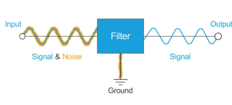
EMI filters are designed to suppress the transmission of selected frequencies of a given signal. One of the most common types of filters in commercial, consumer, and other less critical applications is a simple, low-pass EMI filter, which allows low-frequency signals to pass through while blocking out unwanted, higher frequency noise, as defined by its cutoff frequency, or the frequency at which a filter begins to attenuate part of the signal. Cutoff frequencies typically represent the point at which the signal amplitude is 3 dB below the nominal passband value, and along with frequency response, are directly affected by a filter’s capacitance and inductance values.
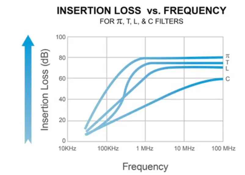
Insertion loss values, which refer to the ratio of the strength of an incoming signal to the strength of the transmitted signal and are typically expressed in decibels, are a prime characteristic of filter efficacy. Ideal insertion loss for the frequency range of interest is 0 dB and is infinite for all other frequencies, but filters are complex devices that are subject to variables including parasitic inductance, parasitic capacitance, component resonance, and circuit resonance; so, it’s impossible to achieve ideal performance. However, once a filter has been designed and produced, users can analyze its insertion loss across a wide range of frequencies to identify the parameters of its performance envelope.
Other characteristics that effect filter performance include equivalent series resistance (ESR), dissipation factor (DF), and Q factor. Low ESR is an indication of a well-de-signed filter that will not dissipate much energy during its operation. Low DF, which takes into account both the ESR and reactance of the filtered capacitor, is another, as it its inverse, Q factor, which is also used to denote filter quality in some industries.
2. CIRCUIT CONFIGURATION
EMI filters are widely available in several different circuit configurations ranging from single grounded capacitors to circuits with up to three elements. Ideal selections de-pend on the unique characteristics and properties of the application at hand, such as device impedance.
3. VOLTAGE CONDITIONS
For optimal EMI protection, EMI filter performance must be matched to corresponding capacitor performance, de-signed and tested for the given circuit’s AC or DC volt-age conditions, and designed to mitigate current leakage. For example, ceramic capacitors have very thin layers of ceramic dielectric that separate the conductive layers from one another to prevent the free flow of electricity and can be designed to withstand voltages in excess of 1,600 VDC. As such, effective filter designs have to em-ploy the appropriate dielectric materials and dimensions best suited for each corresponding capacitor’s unique set of performance requirements.
EMI filters must also be designed and tested for each circuit’s AC or DC voltage conditions. DC filter ratings are not the same as AC filter ratings, so a filter’s ability to successfully withstand high DC voltage does not adequately predict its performance when exposed to high AC voltage and vice versa. For instance, AC-rated filters will often have lower capacitance values to prevent overheating and damage resulting from reactive current heating, while DC-rated filters expected to experience short, irregular bursts of voltage, like those employed in implantable cardiac defibrillators, are likely to undergo a pulsed voltage test to verify capacitor integrity.
In addition to being able to withstand given circuit volt-ages, effective filters also help control current leakage across the capacitor. Although it’s impossible to construct a capacitor that completely prevents this flow of electricity, EMI filters can leverage inherent material properties to mitigate leakage current and its impact on device performance.
4. FILTER CONSTRUCTION
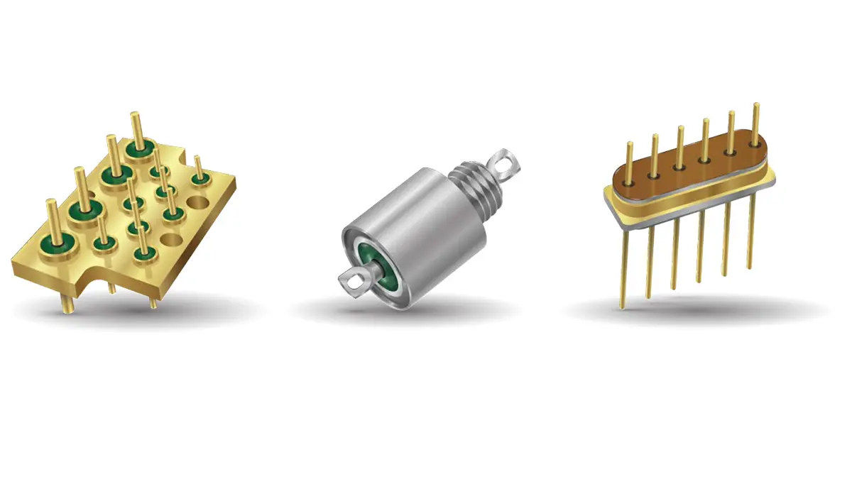
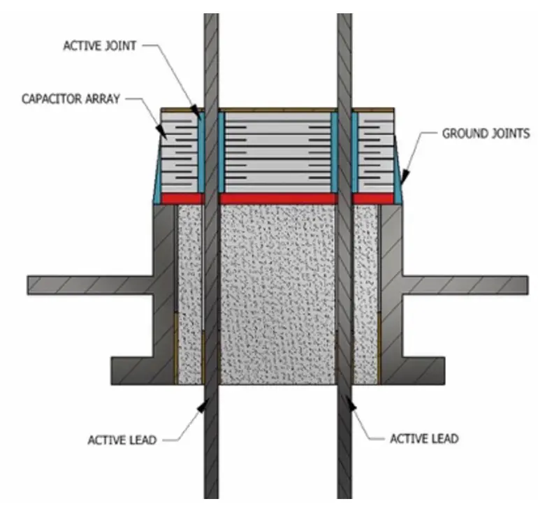
Donut-shaped discoidal capacitors are one of the most common feed-through-style EMI filter constructions. The inside and outside diameters of these circular capacitors act as connection points for the case and the lead and serve as the poles of the capacitor. In applications where space is at a premium, several discoidal capacitors can be integrated into a single piece of ceramic to create a capacitor array. These filtered feedthrough assemblies provide the highest concentration of filters within the small-est physical space and are often employed in miniature, high-density implantable medical devices, as well as size- and weight-restricted commercial and military applications.
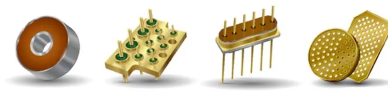
Complex electronic devices often require filtering on multiple signal or power lines. One way to isolate them from each another is to employ a special metal ferrule that both contains and acts as a common ground for multiple filters by connecting their cases together while keeping the pins isolated. Fully tested and assembled feedthrough filter capacitor arrays offer another optimal solution for more complex circuits, as they are widely available in custom shapes and sizes that facilitate seamless, single-step integration into more challenging device designs and reduce the potential for installation errors and resulting component damage. There is no hard limit on the number of capacitors that can be integrated into a single array, but component cost increases with capacitor quantity.
EMI filters are also available in a wide variety of case sizes, lead lengths, and environmental sealing options for broad application suitability, and many filter manufacturers will develop custom designs when existing off-the-shelf options aren’t an ideal fit. Hermetically sealed filters prevent the leakage of gasses and are often employed in aerospace applications, and environmentally sealed filters provide resistance against the ingress of dust, dirt, moisture, and other contaminants and are widely employed in harsh-environment automotive, industrial, medical, defense, and transportation applications.
5. INSTALLATION OPTIONS
Although filters must be installed in an EMI shield, such as a well-grounded conductive enclosure, for optimal performance, device designers can choose from a variety of installation options. Solder-in filters are ideally suited for compact installations, are designed to withstand brief exposure to high soldering temperatures, and typically achieve the best hermeticity of the top three installation styles.
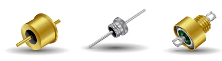
Other leading options include bolt-in filters, which have a threaded, typically hexagonal head, and screw-in cylindrical filters, which have the largest internal volume, can accommodate complex circuits, such as a Pi and T filters, in a single package, and are mounted using separate screws.
In addition to selecting the right installation method for a given application, device designers can further ensure the integrity of the filter both during and after installation by preheating solder joints before exposing them to the full soldering temperature to help mitigate thermal stress and gently handling filter cases to prevent mechanical deformation.
6. TESTING AND INSPECTION
When selecting filters for mission-critical applications, like manned spaceflights and implantable medical de-vices, options should be limited to filters that have been subjected to enhanced electrical and visual inspections and additional testing sequences to further ensure robust, long-lifetime performance. For instance, several military specifications contain extremely specific instructions and performance requirements for electrical, mechanical, and thermal testing procedures and can be useful for validating mission-critical application suit-ability. In addition, stress testing is often conducted on ceramic components since they typically have a high propensity for crack propagation and those with any hint of mechanical instability will generally fail early on and effectively eliminate any inferior parts that could cause future performance issues.
Well-experienced filter manufacturers should offer several different inspection and testing capabilities and help customers identify which procedures are best suited for verifying performance in terms of a given set of application demands.
Actual testing sequences may vary slightly depending on the filter manufacturer and any special device requirements, but often include tests outlined in the MIL-PRF-28861, MIL-PRF-31033, MIL-STD-202, and MIL-STD-220 specifications.
7. COST AND MANUFACTURING CONSIDERATIONS
Filter specifications including circuit complexity, voltage and current ratings, size, temperature resistance, reliability level, and the amount of testing required to verify reliability all impact filter cost to varying degrees. Many of these factors are governed by device-level requirements, but there are a few aspects of filter design that leave room for experienced manufacturers to reduce costs without notably affecting filter function.
Proper material selection is an important element of filter cost because prices and functionality can vary significantly between different material options. For example, the use of palladium rather than platinum for leads or capacitor terminations can result in significant mate-rial cost savings, but can also make installation more difficult. Variables including whether the leads will be soldered, welded, or otherwise inserted into the final device can also affect material selection due to the fact that certain material options are best suited for specific attachment methods. In order to make the best selections, it’s important to consider capacitor dimensions, such as thickness and shape, and to establish a solid understanding of the assembly process environment. Seemingly minor changes to capacitor designs, like capacitance value, can have seriously adverse effects on manufacturing and device design processes and can occasionally require complete filter redesigns.
Additionally, in some cases, device designers may have additional insights that filter manufacturers may not, such as the potential for greater cost savings via simplified or optimized installation methods that would make a costlier, more complex filter design worthwhile. So, it’s important to discuss any potential cost/performance trade-offs early in the design cycle to ensure that a quality product can be specified from available selections or created at a reasonable cost. While some electronic devices will have particularly unique requirements that demand completely custom filters, many devices that require a slightly more complex solution than is already available can utilize an existing filter as a template to achieve a semi-custom design with shorter lead times and lower qualification and per-piece part costs for initial volumes.
ADDITIONAL APPLICATION-SPECIFIC CONSIDERATIONS FOR SELECTING EMI FILTERS
Commercial Filters
Regulations for commercial filters and devices can vary based on the country they’re sold in. For example, some countries restrict the concentration of hazardous materials in electronics and require manufacturers to comply with RoHS or similar standards. Experienced filter designers are well versed in these requirements and can present customers with alternative options, such as employing cadmium-free terminations or conductive polyimide instead of solder.
Rules and regulations regarding the emission of electromagnetic radiation can drive the decision to use a filter as well. In addition to keeping harmful EMI out of a de-vice, filters can also prevent EMI from escaping and interfering with other sensitive equipment in the surrounding environment. Almost every country has regulations that determine the approved type and amount of EMI that devices may generate.
Many countries and companies also enforce regulations regarding the selection of ethical component suppliers. Ethical filter suppliers comply with all labor regulations in their country of operation, as well as with larger international regulations, such as the Modern Slavery Act of 2015, SA8000, the EICC Code of Conduct, and ILO 18000, and may also hold accreditation such as ISO 9001, which can help ensure that suppliers follow ethical manufacturing practices.

Aerospace and Defense Filters
Aerospace and defense electronics must comply with an array of strict rules and regulations that govern almost every aspect of device performance, manufacturing, and testing. In addition, defense companies must often follow strict regulations regarding how they select and audit their suppliers, and may even be limited to a specific list of suppliers that have earned accreditation to certain governments’ military and aerospace specifications. For ex-ample, the United States requires that companies com-ply with applicable export compliance regulations, such as Export Administration Regulations (EAR) and Inter-national Traffic in Arms Regulations (ITAR).
Aerospace and defense suppliers must also follow regulations regarding the security and confidentiality of the products they are manufacturing, as well as any information regarding the product’s intended use or user.
Medical Device Filters
Medical device technology has advanced at an astonishing pace in recent years, offering greater functionality in smaller, lighter-weight form factors designed for increased comfort, ease of use, and environmental resistance. However, these and other sensitive electronic devices are subjected to ever-expanding levels of electromagnetic interference in both medical environments and the increasingly interconnected world at large and, due to the critical nature of their reliability, are at particular risk for harmful interference from various sources of EMI. To ensure high levels of precision and reliability, most medical devices employ EMI filters to minimize noise and maintain signal fidelity.
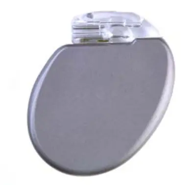
Medical device filters have some of the most stringent spatial requirements and, as such, commonly specify filtered feedthrough arrays or miniature discoidal capacitors, which deliver high-density performance in low-volume packaging. In addition, since the vast majority of wearable and implantable medical devices are battery powered, device designers must select low-power filters to prolong device life. Measuring and minimizing ESR or DF can help keep unnecessary battery drain to a minimum and high insulation resistance (IR) can help minimize current leakage across the capacitor. Modern implantable medical devices typically employ primary cell, non-rechargeable batteries that are designed to last 10 or more years. However, since high-reliability implant battery technology hasn’t quite kept pace with the miniaturization of many other medical components, minimizing power consumption is especially crucial to achieving target battery and device life expectancy.
Early implantable devices like pacemakers were not compatible with magnetic resonance imaging (MRI) due to the impact that such large amounts of EMI would have on device performance, but many designs have since evolved to safely withstand specific levels and durations of MRI exposure.
The test methods that medical device designers use to ensure their devices are MRI-compatible can be proprietary to each company but always require various types of filters. As such, filter manufacturers that supply to the medical device market must carefully consider how their testing procedures and any subsequent MRI exposure could potentially affect characteristics such as lead attachment methods or the selection of internal or external grounding mechanisms.
In addition, several global regulatory bodies impose proprietary series of stringent regulations on medical de-vice manufacturers and their suppliers in an attempt to further ensure patient and operator safety. These can range from exacting design requirements to thorough onsite audits and complex documentation processes. So, it’s critical for medical device designers to select filter manufacturers with a proven track record of regulatory compliance, reliable designs, and quality manufacturing processes. Medical device designers can also benefit from specifying existing filter products whenever possible, as doing so can achieve both significant reductions in device qualification lead-times and cost savings.
CONCLUSION
EMI is emitted by a number of both natural and engineered sources and is a hazard that virtually all electronic devices must be adequately protected from, regardless of application area. Board-level EMI suppression filters are one of the most common electromagnetic compatibility solutions and are widely available in a broad range of sizes, configurations, materials, capabilities, and costs. Although most electronics employ an EMI filter, most also have their own unique sets of application requirements. Factors including capacitance, voltage rating, dimensions, hermeticity, and cost must be carefully balanced to arrive at an optimal end result.
To ensure optimal filter selections, device designers should carefully consider the seven fundamental characteristics of EMI filters addressed here filtering properties, circuit configuration, voltage conditions, construction, installation options, testing and inspection, and manufacturing costs in the context of the application at hand.
Commercial and consumer applications with standard reliability requirements may be able to take advantage of off-the-shelf filter component capabilities, but each application is still likely to require its own unique combination of filter characteristics. These types of applications are also often subject to environmental, EMI radiation, and ethical manufacturing regulations that can vary by country. Higher reliability applications including military, defense, aerospace, and medical applications often require semi-custom modifications to existing filter components or fully custom solutions.
In these instances, it’s vital for device designers and EMI filter designers to communicate and collaborate through-out the design cycle to develop a solution that meets price/performance ratios. Often times, experienced filter designers can help modify an existing solution to help customers achieve slightly more complex solutions than are readily available with shorter lead times and qualification processes, as well as lower per-piece and qualification costs for initial volumes. So, when selecting a filter manufacturer, it’s important to select one that offers several different inspection and testing capabilities and, for higher reliability applications, a verifiable track record of regulatory compliance, reliable designs, and proven manufacturing processes.


