











Passive Components Blog
No Result
View All Result
  • Home
  • News
    • All
    • Aerospace & Defence
    • Antenna
    • Applications
    • Automotive
    • Capacitors
    • Circuit Protection Devices
    • electro-mechanical news
    • Filters
    • Fuses
    • Inductors
    • Industrial
    • Integrated Passives
    • inter-connect news
    • Market & Supply Chain
    • Market Insights
    • Medical
    • Modelling and Simulation
    • New Materials & Supply
    • New Technologies
    • Non-linear Passives
    • Optoelectronics and Isolation
    • Oscillators
    • Passive Sensors News
    • Resistors
    • RF & Microwave
    • Telecommunication
    • Weekly Digest
    Silicon capacitors and integrated passives dossier cover

    Silicon Capacitors and Integrated Passives Dossier Report 10/26

    Samtec automotive interconnect technologies for software-defined vehicle electronics

    Samtec Links Automotive Connector Demands to Software-Defined Cars

    Panasonic Industry PGS graphite heat-spreading technology and passive components for spacecraft thermal management

    Panasonic Targets Space Thermal Design at SPCD 2026

    tungsten-bronze-ceramic-capacitor-stack

    Tungsten bronze capacitors combine high κ and thermal stability

    Bourns MF-ASMF Series surface-mount PPTC resettable fuses in the manufacturer product photograph

    Bourns Announces 0402 PPTC Fuses Target Low-Current Protection

    Conceptual illustration of Littelfuse AQ4315-01ETG and SP4315-01WTG TVS diode applications on high-speed PCB data lines

    Littelfuse Adds Low-Capacitance TVS Diodes for Fast Data Links

    Datasheet-style illustration of a TDK MLJ1608-G multilayer chip inductor with end terminals

    TDK Expands1608 Inductors for Automotive PoC Filters

    Murata electronica 2026 technology preview featuring MGJ2T2 power converters and SCI36LT inertial sensors.

    Murata Previews SiC Power and AI Sensors at electronica 2026

    Ruggedized passive component customization overview covering capacitors, resistors and inductors.

    Ruggedized Passive Components: Reliability Beyond the Datasheet

    Trending Tags

    • Ripple Current
    • RF
    • Leakage Current
    • Tantalum vs Ceramic
    • Snubber
    • Low ESR
    • Feedthrough
    • Derating
    • Dielectric Constant
    • New Products
    • Market Reports
  • Knowledge Blog
  • Dossiers
    • Aerospace and Defense Passive Components Dossier
    • AI Hardware Dossier
    • Automotive Dossier
    • Industrial Robotics Dossier
    • Power Converter Dossier
    • Capacitor Dossier
    • Circuit Protection Dossier
    • Inductor Dossier
    • Resistor Dossier
    • Silicon Capacitors and Integrated Passives Dossier
  • Suppliers
    • Who is Who
  • PCNS
    • PCNS 2025
    • PCNS 2023
    • PCNS 2021
    • PCNS 2019
    • PCNS 2017
  • Events
  • Home
  • News
    • All
    • Aerospace & Defence
    • Antenna
    • Applications
    • Automotive
    • Capacitors
    • Circuit Protection Devices
    • electro-mechanical news
    • Filters
    • Fuses
    • Inductors
    • Industrial
    • Integrated Passives
    • inter-connect news
    • Market & Supply Chain
    • Market Insights
    • Medical
    • Modelling and Simulation
    • New Materials & Supply
    • New Technologies
    • Non-linear Passives
    • Optoelectronics and Isolation
    • Oscillators
    • Passive Sensors News
    • Resistors
    • RF & Microwave
    • Telecommunication
    • Weekly Digest
    Silicon capacitors and integrated passives dossier cover

    Silicon Capacitors and Integrated Passives Dossier Report 10/26

    Samtec automotive interconnect technologies for software-defined vehicle electronics

    Samtec Links Automotive Connector Demands to Software-Defined Cars

    Panasonic Industry PGS graphite heat-spreading technology and passive components for spacecraft thermal management

    Panasonic Targets Space Thermal Design at SPCD 2026

    tungsten-bronze-ceramic-capacitor-stack

    Tungsten bronze capacitors combine high κ and thermal stability

    Bourns MF-ASMF Series surface-mount PPTC resettable fuses in the manufacturer product photograph

    Bourns Announces 0402 PPTC Fuses Target Low-Current Protection

    Conceptual illustration of Littelfuse AQ4315-01ETG and SP4315-01WTG TVS diode applications on high-speed PCB data lines

    Littelfuse Adds Low-Capacitance TVS Diodes for Fast Data Links

    Datasheet-style illustration of a TDK MLJ1608-G multilayer chip inductor with end terminals

    TDK Expands1608 Inductors for Automotive PoC Filters

    Murata electronica 2026 technology preview featuring MGJ2T2 power converters and SCI36LT inertial sensors.

    Murata Previews SiC Power and AI Sensors at electronica 2026

    Ruggedized passive component customization overview covering capacitors, resistors and inductors.

    Ruggedized Passive Components: Reliability Beyond the Datasheet

    Trending Tags

    • Ripple Current
    • RF
    • Leakage Current
    • Tantalum vs Ceramic
    • Snubber
    • Low ESR
    • Feedthrough
    • Derating
    • Dielectric Constant
    • New Products
    • Market Reports
  • Knowledge Blog
  • Dossiers
    • Aerospace and Defense Passive Components Dossier
    • AI Hardware Dossier
    • Automotive Dossier
    • Industrial Robotics Dossier
    • Power Converter Dossier
    • Capacitor Dossier
    • Circuit Protection Dossier
    • Inductor Dossier
    • Resistor Dossier
    • Silicon Capacitors and Integrated Passives Dossier
  • Suppliers
    • Who is Who
  • PCNS
    • PCNS 2025
    • PCNS 2023
    • PCNS 2021
    • PCNS 2019
    • PCNS 2017
  • Events
No Result
View All Result
Passive Components Blog
No Result
View All Result

Fix poor capacitor, inductor, and DC/DC impedance measurements

8.6.2016
Reading Time: 6 mins read
A A

source: EDN article

Steve Sandler -June 07, 2016
When designing or optimizing a VRM (voltage Regulation Module), we need its output impedance data and impedance data for the filter inductors and capacitors for us to have complete simulation models. Unfortunately, vendor data on these components is often incomplete, erroneous, or difficult to decipher in terms of the setup involved to make the measurement. Thus, we often need to collect the data ourselves.

RelatedPosts

Silicon Capacitors and Integrated Passives Dossier Report 10/26

Samtec Links Automotive Connector Demands to Software-Defined Cars

Panasonic Targets Space Thermal Design at SPCD 2026

The measurements need to be performed over the entire frequency range of interest, typically from a few kiloHertz to about 1 GHz, depending on the application. Because of this very wide frequency range, we generally turn to S-parameter based measurements. High performance simulators can directly incorporate the S-parameter component measurements in AC, DC, transient, and harmonic balance simulations while including the finite element PCB models.

While extremely useful, standard S-parameter measurements frequently aren’t sufficient. What’s really needed is an extended range, that is, a partial S2p measurement. I’ll explain why you need it and how to make this improved measurement.

S-parameters are a simple method of performing measurements over a very wide frequency range. The measurement is performed using a fixed resistance port rather than a high impedance probe. Two options are available for measuring impedance with S-parameters. One option is a reflection measurement and the other option is THRU measurement.

One port or two? Why partial?
The reflection, or 1-port, measurement is the simplest because it requires only one cable. But, it also requires a complex calibration, generally consisting of an OPEN calibration, a SHORT calibration, and a LOAD or MATCH calibration of the port used for the measurement. Most VNA’s (vector network analyzers) include the transformation from the S-parameter reflection measurement (S11 or S22) to impedance, but it’s quite simple. Using port 1 as an example, the reflection for a given reference impedance, Zref, (typically 50 Ω) the relationship between S11 and the device impedance is shown in Table 1.

Table 1. 1-Port Transformations

We can perform a 2-port measurement by placing the device to be measured either in series with or in shunt with the measurement ports. Table 2 shows the relationship between S21 and the device impedance for both the series and shunt configuration.

Table 2. 2-Port Transformations.

DC Ground Loop
An additional issue arises for the 2-port shunt-thru measurement due to a DC ground loop, which occurs as a result of the RF ground at the VNA and the series resistance of the interconnecting measurement cables. The Keysight E5061B VNA has a semi-floating input on the low frequency gain-phase ports, eliminating this DC ground loop for low impedance measurements up to 30 MHz. For the E5061B high frequency ports and other VNAs in general, the DC ground loop must be minimized using a common-mode coaxial transformer such as the Picotest J2102A. Otherwise, the low frequency measurements will be inaccurate.

The setup diagrams for these impedance measurement options are shown in Figure 1.

Figure 1. Basic Schematics for the 1-port and 2-port impedance measurements.

The simulations in Figure 2 show the S-parameter magnitude for each measurement technique as a function of the device impedance. All measurements lose sensitivity as the S-parameter magnitude approaches 1.0

Figure 2. S-parameter magnitude as a function of the device impedance.

Figure 3 shows a higher resolution view of the S parameter magnitude from 0.95 to 1.0.

Figure 3. Higher resolution view of the S-parameter magnitude as a function of the device impedance.

Setting the measurable S-parameter (either S11, S22 or S21) to a minimum of 40E-6 allows for a reasonable signal-to-noise margin and a maximum of 0.95. The ranges for each measurement are shown in Table 3.

Table 3. Measurement Impedance ranges.

Which range do we need?
Because we’re typically measuring VRMs, PDN’s (power distribution networks), capacitors, and inductors, the minimum impedance measurement is in the milliOhms range—whether it is inductor DCR (DC resistance), VRM output impedance, or capacitor ESR (equivalent series resistance). This requires the 2-port shunt measurement.

The measured S-parameter file must be valid for the complete simulation frequency range. Establishing the measurement range to be from 1 kHz to 500 MHz and using what I call the “realistic measurement range,” we can determine the maximum inductance or capacitance that can be measured using the 2-port shunt measurement.

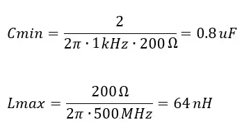
Using the 2-port shunt measurement, the minimum capacitance that can be measured is 800 nF, precluding the measurement of high-frequency decoupling capacitors. The maximum inductance that can be measured at 500 MHz is only 60 nH. Even if the inductor is assumed to have a resonant frequency of 100 MHz, the maximum inductance that can be measured is less than 1 µH, precluding the measurement of ferrite beads and most output filter inductors.

Another issue arises in making this measurement. S21, S11, and S22 are all measuring the same device and therefore the same impedance range. As explained above, the S11 and S22 measurements fall below the range of the 1-port measurement. For example, while measuring an inductor, the DCR will be measured as S11 and S22. While measuring a capacitor, the ESR will be measured using S11 and S22. These 1-port terms will be invalid at low impedance levels typical of the devices. That’s why we need a “partial” 2-port thru measurement. We will only keep the S21 term and remove the S11 and S22 terms because they’re invalid at impedance levels below 0.5 Ω.

Some instruments allow saving the measurement as a Touchstone impedance file, which is a partial 2-port s-parameter file.

Extending the 2-port range
We can scale the measurement using series resistors, effectively increasing the port’s reference impedance. That lets us measure the decoupling capacitors and larger inductors. Figure 4  shows the results of this measurement.

Figure 4. Adding series resistors to extend the impedance range of the 2-port shunt measurement.

For example, adding a 450 Ω series resistor makes the reference impedance 500 Ω, shifting the measurement range up by a factor of 10. In some cases, the added series resistors can be accommodated by using an attenuating transmission line oscilloscope probe. Scaling factors of 1, 5, 10 and 20 are commercially available as 1-port probes. A pair of probes can be used to make a 2-port extended range measurement. The measurement range for various values of series resistors are shown in Table 4.

Table 4. Measurement Impedance ranges for various series resistor values.

The impedance transformation with the series resistors included is shown in Table 5.

Table 5. Impedance transformation including series resistors.

For measurements at either extreme of the measurement range, be sure to perform a full fixture removal calibration or full 1 port calibration on both parts as well as a THRU calibration. If series resistors are included, perform the THRU calibration with the series resistors included in the setup.A 0.1 µF ceramic capacitor is used as an example of the extended range two port impedance measurement. The results are shown up to 30 MHz in Figure 5. The impedance measurement spans the range of more than 1 kΩ and below the 9 mΩ ESR.

Figure 5. Measurement of a 0.1 µF capacitor with RS=200 Ω.

Higher frequency, low impedance measurements are very sensitive to even very small fixture inductance and at high frequency, high impedance measurements are very sensitive to even very small fixture capacitance. A smaller, 1 nF capacitor can eb measured at frequencies up to 1 GHz. Figure 6 shows the results.

Figure 6. The plot shows a measurement of of a 1 nF capacitor at frequenies up to 1 GHz. The resonance results from the capacitor ESL combined with the SMA connector capacitance of approximately 1 pF.

The 850 MHz resonance is the result of approximately 1 pF of excess capacitance from the low-quality SMA connectors. To accurately measure at these frequencies, we need better connectors and/or the excess capacitance needs to be calibrated out of the measurement.

Conclusion
The extended range technique and saving the S21 data only or a Touchstone Z data file provides a method of scaling the measurement to optimize the measurement window. Added benefits are that the extension resistors reduce the loading when measuring lower power VRM’s. This technique can also be used for measuring the output impedance of voltage references and closed loop op-amps and is supported by the Picotest non-invasive stability measurement as well.

Related

Recent Posts

Silicon capacitors and integrated passives dossier cover

Silicon Capacitors and Integrated Passives Dossier Report 10/26

8.10.2026
1
Panasonic Industry PGS graphite heat-spreading technology and passive components for spacecraft thermal management

Panasonic Targets Space Thermal Design at SPCD 2026

8.10.2026
8
tungsten-bronze-ceramic-capacitor-stack

Tungsten bronze capacitors combine high κ and thermal stability

7.10.2026
14
Datasheet-style illustration of a TDK MLJ1608-G multilayer chip inductor with end terminals

TDK Expands1608 Inductors for Automotive PoC Filters

6.10.2026
7
Ruggedized passive component customization overview covering capacitors, resistors and inductors.

Ruggedized Passive Components: Reliability Beyond the Datasheet

6.10.2026
21
YAGEO Group PMT6709NLT and PHT7249NLT GDSC SMD LLC gate-drive transformers for SiC and GaN switching applications

YAGEO Introduces LLC Transformers for SiC and GaN Gate Drives

2.10.2026
25
TDK B3272 series boxed DC-link film capacitors with radial leads for automotive and industrial power-electronics applications

TDK Expanded DC-Link Film Capacitors to Reach +135 °C

2.10.2026
24
Film DC-link capacitor and supercapacitor energy buffer in a high-voltage power converter system

Electrification Raises Demands on DC-Link Capacitors

1.10.2026
29
YAGEO Group high-reliability polymer tantalum capacitor portfolio for aerospace and defence power electronics

YAGEO High-Reliability Polymer Tantalum Capacitors for Aerospace

1.10.2026
38

Upcoming Events

Oct 9
18:00 - 19:00 CEST

Edgewater Research 3Q26 Electronic Components Review Outlook Webinar

Oct 14
17:00 - 18:00 CEST

Live Demo! Discover KYOCERA AVX Antenna Integrator Studio (AIS)

Oct 19
15:00 - 16:00 CEST

ESCC-qualified Pt Temperature Sensors for Space Applications

View Calendar

Popular Posts

  • Buck Converter Design and Calculation

    0 shares
    Share 0 Tweet 0
  • Boost Converter Design and Calculation

    0 shares
    Share 0 Tweet 0
  • LLC Resonant Converter Design and Calculation

    0 shares
    Share 0 Tweet 0
  • Flyback Converter Design and Calculation

    0 shares
    Share 0 Tweet 0
  • Capacitor Charging and Discharging

    0 shares
    Share 0 Tweet 0
  • Resistor Symbols

    0 shares
    Share 0 Tweet 0
  • Audio Capacitors: Choosing Capacitors for Crossover Circuits

    0 shares
    Share 0 Tweet 0
  • Thermistors Basics, NTC and PTC Thermistors

    0 shares
    Share 0 Tweet 0
  • MLCC and Ceramic Capacitors

    0 shares
    Share 0 Tweet 0
  • RF Connector Types: How To Choose the Right One

    0 shares
    Share 0 Tweet 0

Newsletter Subscription


Passive Components Blog

© 2015–2026
All rights reserved

  • Home
  • Privacy Policy
  • EPCI Membership & Advertisement
  • About

No Result
View All Result
  • Home
  • Knowledge Blog
  • Dossiers
  • PCNS

© 2015–2026
All rights reserved










