• Latest
  • Trending
  • All
  • Capacitors
  • Resistors
  • Inductors
  • Filters
  • Fuses
  • Non-linear Passives
  • Applications
  • Integrated Passives
  • Oscillators
  • Passive Sensors
  • New Technologies
  • Aerospace & Defence
  • Automotive
  • Industrial
  • Market & Supply Chain
  • Medical
  • RF & Microwave
  • Telecommunication

High Voltage MLCCs Arc-Over Prevention

1.3.2019

Examining the Influence of ESR and Ripple Current on Selecting the Suitable Capacitor

21.3.2023

SABIC Validates its 150°C Film Foil to Enable Adoption of Film Capacitors in SIC Power Modules

20.3.2023

Outlook of Passive Electronic Components Market for Oil & Gas Electronics in 2023

20.3.2023

Flying Capacitors Explained

17.3.2023

TDK Introduces Compact High-Current Chokes for Automotive and Industrial Applications

16.3.2023

ECIA NA February 2023 Electronic Components Sales Confirms Growth Trend

16.3.2023
  • Home
  • Privacy Policy
  • EPCI Membership & Advertisement
  • About
No Result
View All Result
NEWSLETTER
Passive Components Blog
  • Home
  • NewsFilter
    • All
    • Aerospace & Defence
    • Antenna
    • Applications
    • Automotive
    • Capacitors
    • Circuit Protection Devices
    • Filters
    • Fuses
    • Inductors
    • Industrial
    • Integrated Passives
    • Market & Supply Chain
    • Medical
    • New Materials & Supply
    • New Technologies
    • Non-linear Passives
    • Oscillators
    • Passive Sensors
    • Resistors
    • RF & Microwave
    • Telecommunication

    Examining the Influence of ESR and Ripple Current on Selecting the Suitable Capacitor

    SABIC Validates its 150°C Film Foil to Enable Adoption of Film Capacitors in SIC Power Modules

    Outlook of Passive Electronic Components Market for Oil & Gas Electronics in 2023

    Flying Capacitors Explained

    TDK Introduces Compact High-Current Chokes for Automotive and Industrial Applications

    ECIA NA February 2023 Electronic Components Sales Confirms Growth Trend

    Investigating Modeling Techniques of Class II Ceramic Capacitors Losses for High Voltage and Current Applications

    TDK Extends Range of Industrial Single Pair Ethernet (SPE) Inductors

    Premo Unveils New series of 11kW 3-Phase On-Board Charger Transformers

    Trending Tags

    • Ripple Current
    • RF
    • Leakage Current
    • Tantalum vs Ceramic
    • Snubber
    • Low ESR
    • Feedthrough
    • Derating
    • Dielectric Constant
    • New Products
    • Market Reports
  • VideoFilter
    • All
    • Antenna videos
    • Capacitor videos
    • Filter videos
    • Fuse videos
    • Inductor videos
    • Non-linear passives videos
    • Oscillator videos
    • Passive sensors videos
    • Resistor videos
    • Sensors

    Investigating Modeling Techniques of Class II Ceramic Capacitors Losses for High Voltage and Current Applications

    Understanding Basics of Current Sense Resistors

    What Decoupling Capacitor Value To Use And Where To Place Them

    How to Measure Rated Current on Power Inductors

    LTspice Simulation of a Spark-Gap Circuit Protection Surge Arrester

    Approximate Inductor Design Using Two Alternative Cores

    1kW Phase Shift Full Bridge Converter Design and Simulation

    Multiphase Buck Trans-Inductor Voltage Regulator (TLVR) Explained

    Smart Power Distribution Unit Architecture and Inductor Losses

    Trending Tags

    • Capacitors explained
    • Inductors explained
    • Resistors explained
    • Filters explained
    • Application Video Guidelines
    • EMC
    • New Products
    • Ripple Current
    • Simulation
    • Tantalum vs Ceramic
  • Knowledge Blog
  • Suppliers
    • Preferred Suppliers
    • Who is Who
  • Events
No Result
View All Result
Passive Components Blog
No Result
View All Result

High Voltage MLCCs Arc-Over Prevention

1.3.2019
Reading Time: 5 mins read
0 0
0
SHARES
892
VIEWS

Source: Electronic Products article

By Reggie Philips, senior product manager, KEMET. Innovative arc-over prevention enables compact, high-voltage surface-mount MLCCs to deliver a cost-effective and space-saving solution for emerging applications in EVs or renewable-energy generation.

RelatedPosts

Examining the Influence of ESR and Ripple Current on Selecting the Suitable Capacitor

SABIC Validates its 150°C Film Foil to Enable Adoption of Film Capacitors in SIC Power Modules

Outlook of Passive Electronic Components Market for Oil & Gas Electronics in 2023

In applications in which energy conservation is critical, such as wind or solar inverters or electric-vehicle (EV) powertrains, distributing power at high voltage can help to reduce I2R losses. The DC link supplying the inverter can be 3 V to 400 V in an EV application, for example, or even higher for wind or solar-power conditioning. However, high operating voltages like these bring additional safety challenges not only for end users but also for components — even those with a suitable voltage rating stamped on the case.

Let’s take a look at how multi-layer ceramic capacitors (MLCCs), which are often used for filtering, decoupling, or snubbing, can be affected by an applied bias of several hundred volts.

The accepted laws of physics tell us that a high MLCC voltage rating and small package size are mutually incompatible: Increasing the voltage rating demands a thicker dielectric layer between plates, which, in turn, increases the size of the component. Even so, demand for small and lightweight power units require high capacitance and high voltage ratings within smaller and smaller package sizes. Designers of EV inverters or wind or solar microgenerators typically seek capacitors such as X7R type MLCCs in 0603 and 0805 case sizes, with voltage ratings of 500 V, 630 V, or 1,000 VDC.

Preventing arc-over damage and destruction

Component makers can go some way toward satisfying these demands with better-performing capacitor materials and construction techniques. In practice, however, factors such as creepage (the natural spreading of an electric field across a dielectric surface) and the tendency of a strong electric field to cause ionization of the surrounding air, as illustrated in Fig. 1, threaten the safety of components operated at high voltages.

When ionization occurs, if the applied voltage bias exceeds the inception voltage of the ionized air, a conductive path can form between device terminals or electrodes at different potentials, resulting in corona discharge, or arcing.

Featured Image Fig. 1: Ionization establishes conditions for terminal-terminal or terminal-electrode arcing.

The inception voltage at which arcing can occur is influenced by a variety of factors including atmospheric temperature and pressure, humidity, and termination creepage distance. The creepage distance, in turn, is affected by the presence of contaminants on the component surface, such as conductive dust particles or accumulated moisture. Ceramic materials that have high dielectric constant, such as X7R materials, have higher porosity — manifested as voids in the material surface — than other dielectrics, such as C0G. These voids tend to harbor moisture and dust, thereby making the component more vulnerable to arcing.

Arcing between terminals can be survivable, although repeated corona discharge across the surface of the device causes carbonized tracks to form and, over time, establish conductive paths. As discharges continue to occur, this will eventually result in short-circuit failure.

More immediately problematic is the possibility for discharge to occur between outer parts of the component and the first internal counter electrode sitting at the opposite potential, as depicted in Fig. 2. This usually causes rapid dielectric breakdown, resulting in short-circuit failure; often accompanied by a quite spectacular destruction of the capacitor.


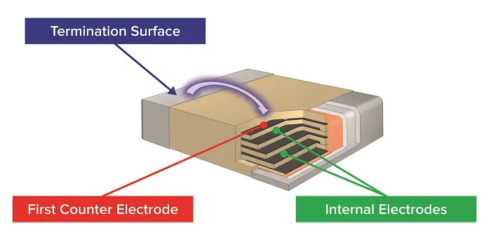
Fig. 2: Arcing between terminal and first counter electrode usually causes rapid capacitor failure.

Historically, capacitor manufacturers and materials specialists have developed various techniques to mitigate the causes of ionization and corona discharge. One of these is to coat the MLCC with a high-insulation polymer or glass-like coating to create a smooth and non-porous surface that provides minimal opportunity for contaminants or moisture to accumulate.

Although this technology has proven to be effective, there are several drawbacks, including the cost of the material and the additional process overheads to apply it. Moreover, the effectiveness of the coating can be compromised if the component body is not fully encapsulated or if the coating becomes damaged.

In addition, if the device is pre-coated, the board designer must ensure that the coating material is compatible with other materials used in the assembly. On the other hand, if the coating is applied after assembly, care must be taken to ensure that there are no voids or gaps, such as in the areas underneath components. These compromise the integrity of the coating and can allow the same arcing potential as an uncoated device.

Floating electrode

Alternatively, the capacitor’s ability to withstand a high applied electric field can be increased by adapting the internal structure.

One example is the cascading internal electrode design. Otherwise known as floating-electrode or serial-capacitor technology, this approach raises the voltage rating in the same way as connecting multiple capacitors in series and effectively increases the creepage distance, reducing the possibility of arcing when a high electric field strength is applied.

The floating-electrode design also provides effective mitigation of flex cracks by preventing a crack from crossing any pair of opposing electrodes and, thus, causing a short circuit. A flex-related crack may only cause a loss of capacitance or a safe open-circuit failure. One disadvantage is that the serial-capacitor approach reduces the effective capacitance, as would connecting discrete capacitors in series.

Internal shielding

A more recent development is to add a shield electrode inside the device, which sits at the same potential as the nearest terminal and extends toward the opposite terminal, as shown in Fig. 3. This can be imagined as being like a Faraday cage and allows a more conventional electrode layout compared to, say, the series-capacitor construction. Hence, the capacitance can be higher for a given voltage rating and device size. In addition, the shield electrode is compatible with flexible terminations to prevent stress cracking.


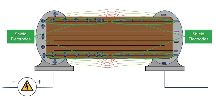
Fig. 3: The shield electrode reduces field strength in the region of the capacitor surface and first counter electrode.

When a high-voltage bias exceeding the inception voltage of ionized air around the capacitor is applied across the terminals, the presence of this shield electrode prevents corona discharge from causing breakdown of the dielectric between the termination and first counter electrode, thereby protecting against the rapid short-circuit failure mode described in Fig. 2.

Because the shield electrode is at the same potential as the nearest terminal, the field concentration is localized in the shield electrodes rather than the termination surface and respective first counter electrode. This minimizes the difference in potential along the surface of the chip and increases the creepage-distance capability. As a result, even devices in small case sizes, or built with a high-porosity dielectric such as X7R, can benefit from increased immunity to arcing and the associated possibility of damage or device failure.

An example of a shield electrode design is KEMET’s ArcShield family of arc-resistant MLCCs that offer high voltage and high capacitance in small EIA-standard case sizes from 0603 to 1812 in commercial or AEC-Q200 automotive grades. Capacitance values range up to 0.33 µF at 500 Vdc, 0.15 µF at 630 Vdc, and 0.10 µF at 1,000 Vdc.

Conclusion

With the addition of a shield electrode, high-capacitance MLCCs up to 1,000 V in small chip-sized packages can resist arc-over discharge and greatly improve the reliability of high-voltage circuitry in applications such as EVs and renewable-energy generation. A shield electrode design delivers permanent protection and overcomes the drawbacks of conventional measures such as cascading electrodes or conformal coating.


Related Posts

Capacitors

Examining the Influence of ESR and Ripple Current on Selecting the Suitable Capacitor

21.3.2023
35
Capacitors

SABIC Validates its 150°C Film Foil to Enable Adoption of Film Capacitors in SIC Power Modules

20.3.2023
13
Market & Supply Chain

Outlook of Passive Electronic Components Market for Oil & Gas Electronics in 2023

20.3.2023
14

Upcoming Events

Mar 19
March 19 - March 23

APEC 2023

Mar 22
14:00 - 15:00 CET

Parasitic Components in Power Converters – Fundamentals and Measurements Rohde & Schwarz Webinar

Apr 3
April 3 @ 12:00 - April 4 @ 14:00 CEST

Microelectronic Packaging Failure Modes and Analysis

View Calendar

Popular Posts

  • What is a Dielectric Constant of Plastic Materials ?

    4 shares
    Share 4 Tweet 0
  • Ripple Current and its Effects on the Performance of Capacitors

    3 shares
    Share 3 Tweet 0
  • Understanding High-Precision Resistor Temperature Coefficient of Resistance

    0 shares
    Share 0 Tweet 0
  • Capacitor Selection for Coupling and Decoupling Applications

    28 shares
    Share 28 Tweet 0
  • Leakage Current Characteristics of Capacitors

    0 shares
    Share 0 Tweet 0
  • How to Choose the Right Inductor for DC-DC Buck Applications

    0 shares
    Share 0 Tweet 0
  • Why Low ESR Matters in Capacitor Design

    0 shares
    Share 0 Tweet 0
  • Dielectric Constant and its Effects on the Properties of a Capacitor

    7 shares
    Share 7 Tweet 0

Newsletter Subscription


PCNS Call for Papers !

Archive

2022
2021
2020
2019
2018
2017

Symposium

Passive Components Networking Symposium

Passives e-Learning

Knowledge Blog

  • Home
  • Privacy Policy
  • EPCI Membership & Advertisement
  • About

© EPCI - Premium Passive Components Educational and Information Site

No Result
View All Result
  • Home
  • News
  • Video
  • Knowledge Blog
  • Preferred Suppliers
  • Events

© EPCI - Premium Passive Components Educational and Information Site

Welcome Back!

Login to your account below

Forgotten Password?

Retrieve your password

Please enter your username or email address to reset your password.

Log In
This website uses cookies. By continuing to use this website you are giving consent to cookies being used. Visit our Privacy and Cookie Policy.