Passive Components Blog
No Result
View All Result
  • Home
  • NewsFilter
    • All
    • Aerospace & Defence
    • Antenna
    • Applications
    • Automotive
    • Capacitors
    • Circuit Protection Devices
    • electro-mechanical news
    • Filters
    • Fuses
    • Inductors
    • Industrial
    • Integrated Passives
    • inter-connect news
    • Market & Supply Chain
    • Market Insights
    • Medical
    • Modelling and Simulation
    • New Materials & Supply
    • New Technologies
    • Non-linear Passives
    • Oscillators
    • Passive Sensors News
    • Resistors
    • RF & Microwave
    • Telecommunication
    • Weekly Digest

    Wk 22 Electronics Supply Chain Digest

    Vishay Releases High‑Current Radial Inductors up to 209 A

    May 2026 Interconnect, Passives and Electromechanical Components Market Insights

    Passive Components Enable Safe and Reliable ADAS Architectures

    Current Sense Transformer Datasheet and Design‑in Guide

    Designing a USB Type‑C Flyback Planar Transformer with Frenetic’s Planar Tool

    YMIN Releases Square Supercapacitors for AI Server Power System

    Exxelia Extends Temperature Range of its PP Film Capacitors to 140C

    How Long-Term Storage Causes Aging in Electronic Components

    Trending Tags

    • Ripple Current
    • RF
    • Leakage Current
    • Tantalum vs Ceramic
    • Snubber
    • Low ESR
    • Feedthrough
    • Derating
    • Dielectric Constant
    • New Products
    • Market Reports
  • VideoFilter
    • All
    • Antenna videos
    • Capacitor videos
    • Circuit Protection Video
    • Filter videos
    • Fuse videos
    • Inductor videos
    • Inter-Connect Video
    • Non-linear passives videos
    • Oscillator videos
    • Passive sensors videos
    • Resistor videos

    Current Sense Transformer Datasheet and Design‑in Guide

    Designing a USB Type‑C Flyback Planar Transformer with Frenetic’s Planar Tool

    Magnetics Design in High‑Frequency GaN Converters

    Qi2 Wireless Charging: Inductors, Capacitors and EMC Filters

    Two‑capacitor paradox explained for engineers

    Capacitances of Nonlinear MLCCs: What Datasheets Don’t Tell You

    Tapped Inductor Buck Converter Fundamentals

    Planar vs Conventional Transformer: When it Make Sense

    Modeling Fringing Field Losses in Inductors & Transformers

    Trending Tags

    • Capacitors explained
    • Inductors explained
    • Resistors explained
    • Filters explained
    • Application Video Guidelines
    • EMC
    • New Products
    • Ripple Current
    • Simulation
    • Tantalum vs Ceramic
  • Knowledge Blog
  • DossiersNew
  • Suppliers
    • Who is Who
  • PCNS
    • PCNS 2025
    • PCNS 2023
    • PCNS 2021
    • PCNS 2019
    • PCNS 2017
  • Events
No Result
View All Result
Passive Components Blog
No Result
View All Result

Minimize Restrikes When Switching Capacitor Banks

15.3.2019
Reading Time: 3 mins read
A A
Silhouette of transformers over yellow sunset sky

Silhouette of transformers over yellow sunset sky

Source: T&D World article

by: Southern States. High power transmission reliability considerations when switching capacitor banks. Minimize or eliminate restrikes when de-energizing capacitor banks.

RelatedPosts

Wk 22 Electronics Supply Chain Digest

Vishay Releases High‑Current Radial Inductors up to 209 A

May 2026 Interconnect, Passives and Electromechanical Components Market Insights

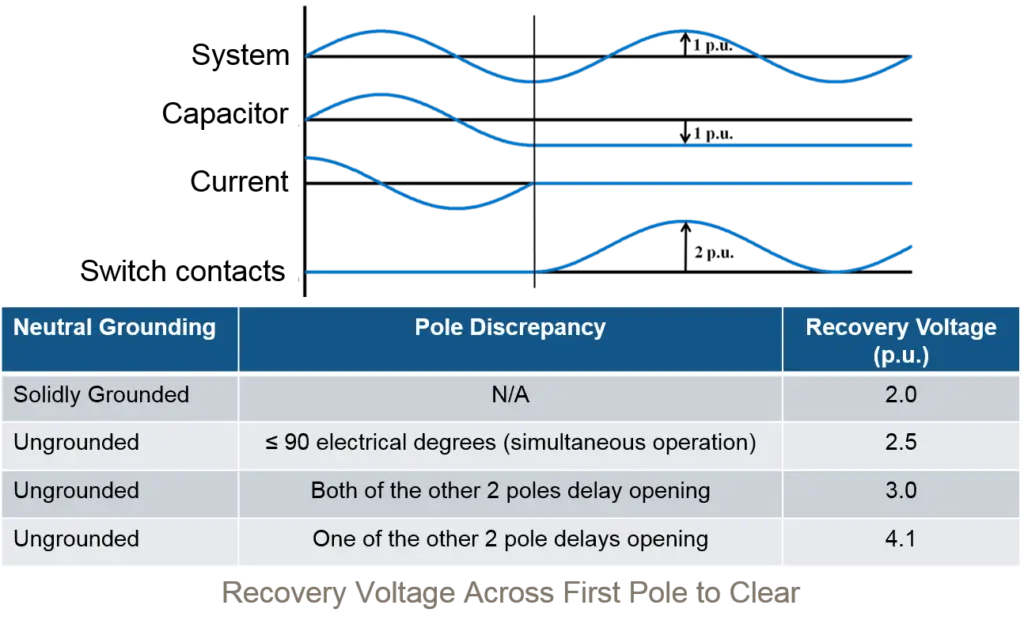
Restrikes or re-ignitions occur when the dielectric strength of the open gap, during contact parting, is not great enough to withstand the recovery voltage across the open gap. With a capacitive load, the current waveform leads the voltage waveform by 90°. The current is interrupted close to the zero crossing when the voltage is at its maximum value. The supply side voltage is relatively unaffected following the interruption, but the voltage of the capacitor bank becomes trapped maintaining the peak voltage level (very low rate of decay) that was present at the time of current interruption.The initial low rate of rise of the recovery voltage and the low level of current being switched make it easy for the switching device to interrupt.

Since the level of the currents being switched are low, the switching device, which is often a general purpose device such as a power circuit breaker or vacuum interrupter, may interrupt the current at a point where the contact separation and parting speed is not sufficient to withstand the voltage difference across the contacts leading to a restrike and the resumption of current flow. Single restrike overvoltages can approach 3 PU.


Restrikes cause cascading overvoltages that can lead to: Ruptured capacitor cans, Blown Fuses, Failed Arrestors, External equipment flashovers, and contact wear that may lead to interrupter dielectric failures.

Minimize Voltage and Current Transients when Energizing capacitor banks

When a capacitor bank is energized, there is an immediate drop in system voltage toward zero, followed by a fast voltage recovery that is superimposed on the system 60 Hz fundamental waveform. This recovery voltage can reach a peak of 2.0 p.u. at frequencies between 300 Hz and 1000 Hz.

While these transients are not typically harmful to utility equipment, they may be troublesome to some customers’ sensitive equipment. The transients often show up a significant distance from the capacitor bus as the high frequency transients pass through transformers and are magnified by capacitor banks located on the distribution system or the at the customers location. The resulting over-voltages can cause nuisance tripping of adjustable speed drives, computer network problems, as well as customer equipment damage or failure. It is generally accepted that transients maintained below about 1.2 p.u. will not impact the customer. Some form of control is necessary to achieve this performance.

When capacitor banks are installed in a back-to-back arrangement (two or more capacitors close to each other), the energization of the second bank looks like a short circuit to the first bank. This causes the first capacitor bank to discharge into the second capacitor bank resulting in high inrush currents. These in-rush currents can reduce the life of the capacitor switching device. On grounded capacitor banks, transient currents may flow in the ground mat causing potential problems with electronic equipment in the substation because of induced voltage in the control voltage supply.

A Special Purpose Solution for Switching Capacitor Banks

The use of a product designed specifically for an application is often the most economical and effective solution. This holds true when switching shunt capacitor banks, as the use of general purpose switching devices, often requiring the application of arrestors, inrush reactors, POW Switching controls, or pre-insertion inductors, can potentially affect performance efficiency, cause increased maintenance and reduce cost effectiveness.

Utilizing closing resistors to minimize voltage transients and inrush currents has become a widely accepted methodology for effective and reliable capacitor bank switching. One field proven approach, developed by Southern States, has been the use of a two-stage switching device, which momentarily introduces an inductance into the circuit, along with an interrupter designed specifically for interrupting capacitive currents.

Related

Recent Posts

Vishay Releases High‑Current Radial Inductors up to 209 A

29.5.2026
13

May 2026 Interconnect, Passives and Electromechanical Components Market Insights

29.5.2026
57

Passive Components Enable Safe and Reliable ADAS Architectures

28.5.2026
53

Current Sense Transformer Datasheet and Design‑in Guide

27.5.2026
46

Designing a USB Type‑C Flyback Planar Transformer with Frenetic’s Planar Tool

27.5.2026
28

YMIN Releases Square Supercapacitors for AI Server Power System

27.5.2026
45

Exxelia Extends Temperature Range of its PP Film Capacitors to 140C

27.5.2026
37

How Long-Term Storage Causes Aging in Electronic Components

26.5.2026
94

Nichicon Presents Self-Charging LTO Board for Maintenance-Free IoT Nodes

26.5.2026
24

Upcoming Events

Jun 2
16:00 - 17:00 CEST

Calculation, Simulation and Measurement of 800V EMC Filters

Jun 16
16:00 - 17:00 CEST

EMC with EMC – EMC‑compliant design with electromechanical connectors

View Calendar

Popular Posts

  • Buck Converter Design and Calculation

    0 shares
    Share 0 Tweet 0
  • Boost Converter Design and Calculation

    0 shares
    Share 0 Tweet 0
  • Flyback Converter Design and Calculation

    0 shares
    Share 0 Tweet 0
  • MLCC and Ceramic Capacitors

    0 shares
    Share 0 Tweet 0
  • LLC Resonant Converter Design and Calculation

    0 shares
    Share 0 Tweet 0
  • Capacitor Charging and Discharging

    0 shares
    Share 0 Tweet 0
  • What Electronics Engineer Needs to Know About Passive Low Pass Filters

    0 shares
    Share 0 Tweet 0
  • Dual Active Bridge (DAB) Topology

    0 shares
    Share 0 Tweet 0
  • Ripple Current and its Effects on the Performance of Capacitors

    3 shares
    Share 3 Tweet 0
  • SEPIC Converter Design and Calculation

    0 shares
    Share 0 Tweet 0

Newsletter Subscription


Passive Components Blog

© EPCI - Leading Passive Components Educational and Information Site

  • Home
  • Privacy Policy
  • EPCI Membership & Advertisement
  • About

No Result
View All Result
  • Home
  • Knowledge Blog
  • Dossiers
  • PCNS

© EPCI - Leading Passive Components Educational and Information Site

This website uses cookies. By continuing to use this website you are giving consent to cookies being used. Visit our Privacy and Cookie Policy.
Go to mobile version