Passive Components Blog
No Result
View All Result
  • Home
  • NewsFilter
    • All
    • Aerospace & Defence
    • Antenna
    • Applications
    • Automotive
    • Capacitors
    • Circuit Protection Devices
    • electro-mechanical news
    • Filters
    • Fuses
    • Inductors
    • Industrial
    • Integrated Passives
    • inter-connect news
    • Market & Supply Chain
    • Market Insights
    • Medical
    • Modelling and Simulation
    • New Materials & Supply
    • New Technologies
    • Non-linear Passives
    • Oscillators
    • Passive Sensors News
    • Resistors
    • RF & Microwave
    • Telecommunication
    • Weekly Digest

    May 2025 Interconnect, Passives and Electromechanical Components Market Insights

    HIROSE Releases New Field-Assembly Communication Connectors

    Coilcraft Unveils 165C High-Temperature Coupled Inductors

    Bourns Releases SMD NTC Thermistors for Thermal Sensing

    Wk 22 Electronics Supply Chain Digest

    Samsung Electro-Mechanics High Capacitance MLCCs for ADAS SoCs

    Murata Expands its Automotive Common Mode Choke Coils to 150C and High Current Capability

    Bourns Releases New Current Transformer

    Skeleton Releases GrapheneGPU to Reduce AI Energy Consumption by 44% and Boosts Power by 40%

    Trending Tags

    • Ripple Current
    • RF
    • Leakage Current
    • Tantalum vs Ceramic
    • Snubber
    • Low ESR
    • Feedthrough
    • Derating
    • Dielectric Constant
    • New Products
    • Market Reports
  • VideoFilter
    • All
    • Antenna videos
    • Capacitor videos
    • Circuit Protection Video
    • Filter videos
    • Fuse videos
    • Inductor videos
    • Inter-Connect Video
    • Non-linear passives videos
    • Oscillator videos
    • Passive sensors videos
    • Resistor videos

    Coupled Inductors Circuit Model and Examples of its Applications

    Inductor Resonances and its Impact to EMI

    Highly Reliable Flex Rigid PCBs, Würth Elektronik Webinar

    Causes of Oscillations in Flyback Converters

    How to design a 60W Flyback Transformer

    Modeling and Simulation of Leakage Inductance

    Power Inductor Considerations for AI High Power Computing – Vishay Video

    Coupled Inductors in Multiphase Boost Converters

    VPG Demonstrates Precision Resistor in Cryogenic Conditions

    Trending Tags

    • Capacitors explained
    • Inductors explained
    • Resistors explained
    • Filters explained
    • Application Video Guidelines
    • EMC
    • New Products
    • Ripple Current
    • Simulation
    • Tantalum vs Ceramic
  • Knowledge Blog
  • Suppliers
    • Who is Who
  • Events
No Result
View All Result
Passive Components Blog
No Result
View All Result

MLCCs for Electrostatic Discharge (ESD) Protection in Automotive Applications, Vishay White Paper

13.7.2020
Reading Time: 5 mins read
A A

Vishay Intertechnology released white paper on use of MLCCs as electrostatic discharge protection in automotive environment. Authors Thomas Wächter, Brian Ward, Eli Bershadsky, and Oded Shiek of Vishay Vitramon.

Today’s automobiles use increasingly more electrical and electronic components. Computers now control many automotive functions to the point that traditional mechanical and pneumatic systems are almost obsolete. Proper functioning of all car electronics depends on eliminating or minimizing the effects of the electrostatic discharge (ESD) phenomenon, which can be harmful to the circuit components.

RelatedPosts

May 2025 Interconnect, Passives and Electromechanical Components Market Insights

HIROSE Releases New Field-Assembly Communication Connectors

Coilcraft Unveils 165C High-Temperature Coupled Inductors

Prevention of damage to the electronic circuit can be accomplished using multiple suppression devices. Multilayer ceramic capacitors (MLCCs) are one of the solutions used to protect components from ESD damage. Since integrated circuits (ICs) are most prone to damage by ESD, MLCCs are placed close to the board connection contacts or directly next to the IC connections in order to absorb and then level the unwanted voltage spikes.

MLCCs of different capacitance values are used at different places in the circuit according to its design: high capacitance MLCCs shunt out high voltage bursts and low capacitance MLCCs are used in circuits where fast responses are required. The origin of the voltage burst could be human touch during manufacturing of the circuit board or operation of the car’s electrical systems. The surge could also come from other equipment that contacts the susceptible circuits.

Different standards based on models of discharge originated by the human body or by machines have been developed to define the level of the ESD protection provided by the MLCCs.

Today there are two major standards addressing the ESD test methods used for validation of MLCCs:

  • AEC-Q200 Automotive Electronic Council human body model (HBM) electrostatic discharge (ESD) test rev. B
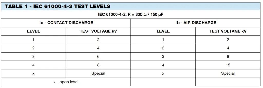
  • IEC 61000-4-2 International Commission; electrostatic discharge immunity test

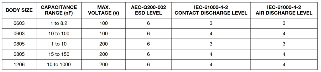
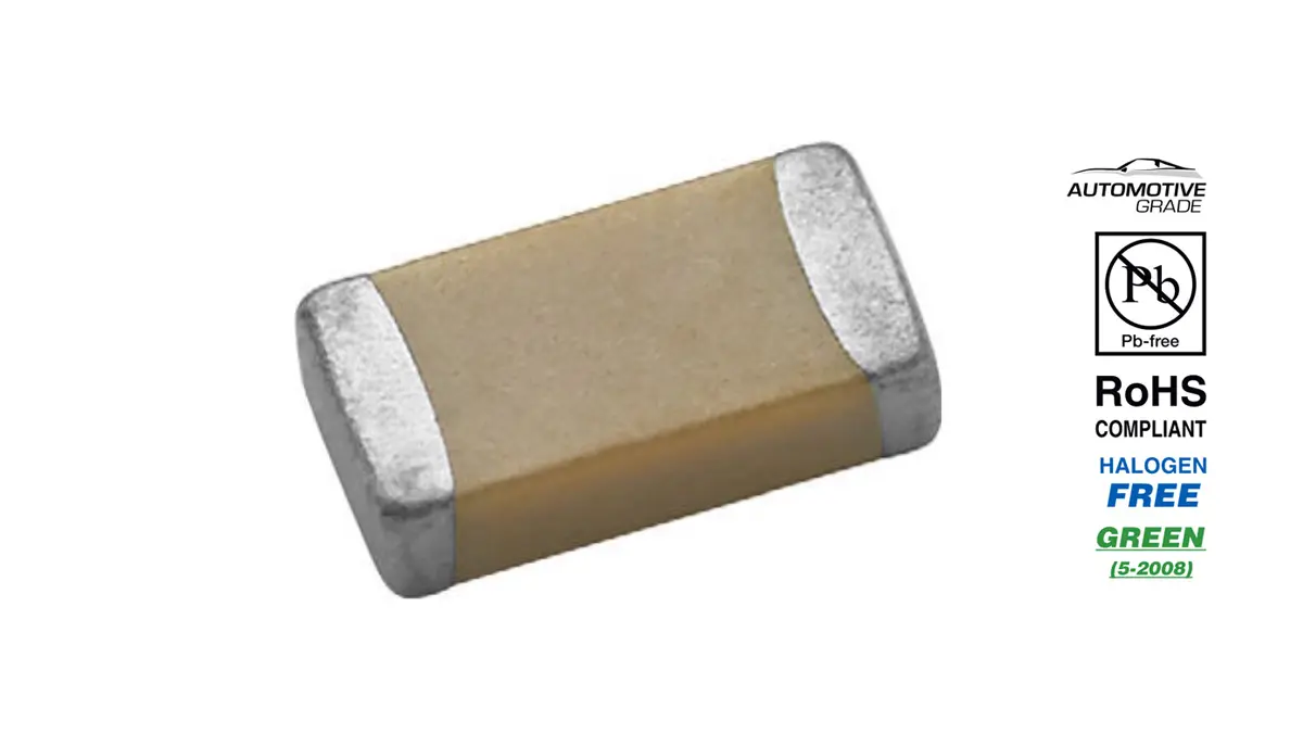
Vishay recently released a new series of MLCCs designed for ESD protection in the automotive industry. These capacitors are manufactured with X7R ceramic in 0603, 0805, and 1206 case sizes using precious metal electrodes (PME) and a wet build up process.

Capacitors manufactured from the wet buildup are characterized by high reliability. All capacitors meet Vishay Green and RoHS / ELV requirements and can be supplied with different types of terminations.For a capacitor to be effective in ESD suppression, it must not be damaged by the ESD strike. So, to test a capacitor, it is exposed to one of the surges defined in the specification, using a circuit as depicted in Figure 1.

Fig. 1 – ESD Test Setup

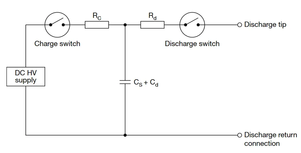
The choice of parameter values in that circuit (charge voltage, charge capacitor, discharge resistor) are chosen to meet the definition of the specific waveform under evaluation. The parameters of the device under test (capacitance, dissipation factor(DF), and insulation resistance (IR)) are measured before and after the application of the surge.

A decrease of capacitance below the defined capacitance or decrease of IR by one degree of order of magnitude are indications of ESD failure in the capacitor.

The typical causes of ESD failure are poor capacitor design, existence of the defects, loss of connection of electrodes with termination pads, etc. Changes in these parameters determine whether the capacitor can pass the surge test.

To establish the AEC-Q200-002 ESD level, parts are tested at increasing severity levels until a failure occurs. A flowchart of this process is shown in Figure 2.

Fig. 2 – AEC-Q200-002 Rev. B – HBM ESD Test Flow Diagram(DC – Direct Contact, AD – Air Discharge

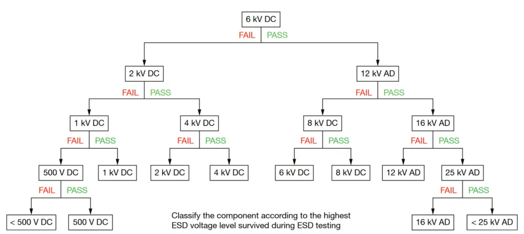
Following this process, the part receives the rating at the last level it passes. For IEC-61000-4-2, parts are tested at the different severity levels (Table 1). Successful performance of the test is achieved using the criteria described in the paragraph above to determine the rating level.

The MLCC protects components by absorbing the energy of the ESD pulse, thus diverting it from the sensitive electronic components. A key factor in how much energy the MLCC can absorb is its capacitance: the energy absorbed is proportional to the capacitance value.

Complicating this scenario is that the capacitance is not constant for the Class II materials used for these MLCCs. In fact, as the voltage applied increases, the effective capacitance decreases. This is known as the Voltage Coefficient of Capacitance, or VCC.

Fig. 3 – Typical VCC of Vishay vs. Competitors 0603, 1 nF, X7R Capacitor

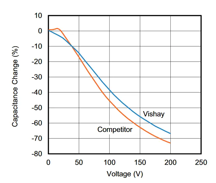
The material used to build the Vishay MLCCs results in a product with better VCC than products built on the material commonly used in the market, as shown in Figure 3.

That means that the Vishay part retains more capacitance at voltage than typical MLCCs – which means more energy absorbed in the MLCC and less transmitted to the sensitive electronic components. Testing of the Vishay MLCCs has produced a series of ESD suppression MLCCs across three body sizes and many capacitance values. A summary of the offering is presented below:

Related

Source: Vishay Vitramon

Recent Posts

Samsung Electro-Mechanics High Capacitance MLCCs for ADAS SoCs

30.5.2025
27

Skeleton Releases GrapheneGPU to Reduce AI Energy Consumption by 44% and Boosts Power by 40%

29.5.2025
40

VINATech Expands Aluminum Capacitor Portfolio with Acquisition of Enesol

28.5.2025
68

Supercapacitors Benefits in Industrial Valve Fail-Safe Control Systems

26.5.2025
32

Samsung Electro-Mechanics Releases High-Capacitance MLCCs for AI Server Applications

21.5.2025
63

Coupled Inductors Circuit Model and Examples of its Applications

21.5.2025
89

Würth Elektronik Introduces LTspice Models for ESD Products

21.5.2025
50

Littelfuse Gate Driver Integrates Diode and Current Limit Resistor in Compact IC

21.5.2025
22

Capacitor Ripple Current Testing: A Design Consideration

21.5.2025
76

Inductor Resonances and its Impact to EMI

16.5.2025
78

Upcoming Events

Popular Posts

  • Buck Converter Design and Calculation

    0 shares
    Share 0 Tweet 0
  • Flyback Converter Design and Calculation

    0 shares
    Share 0 Tweet 0
  • Boost Converter Design and Calculation

    0 shares
    Share 0 Tweet 0
  • What is a Dielectric Constant and DF of Plastic Materials?

    4 shares
    Share 4 Tweet 0
  • LLC Resonant Converter Design and Calculation

    0 shares
    Share 0 Tweet 0
  • Dual Active Bridge (DAB) Topology Explained

    0 shares
    Share 0 Tweet 0
  • What Electronics Engineer Needs to Know About Passive Low Pass Filters

    0 shares
    Share 0 Tweet 0
  • Coefficient of Linear Thermal Expansion on Polymers Explained

    0 shares
    Share 0 Tweet 0
  • Flying Capacitors Explained

    0 shares
    Share 0 Tweet 0
  • Dissipation Factor of Plastic Materials Explained

    0 shares
    Share 0 Tweet 0

Newsletter Subscription


Passive Components Blog

© EPCI - Leading Passive Components Educational and Information Site

  • Home
  • Privacy Policy
  • EPCI Membership & Advertisement
  • About

No Result
View All Result
  • Home
  • Knowledge Blog
  • Premium Suppliers

© EPCI - Leading Passive Components Educational and Information Site

This website uses cookies. By continuing to use this website you are giving consent to cookies being used. Visit our Privacy and Cookie Policy.
Go to mobile version