


Downsizing and footprint reduction are constant requirements of the market for all applications or equipment and the relative components. Film capacitors are not an exception and time by time is required to reduce the components dimension maintaining the same rated voltage and performances. Decreasing the volume of the components, one of the consequences is a reduction of the power dissipation by its surfaces and therefore a final increasing of its working temperature.
The paper was presented by Evangelista Boni, KEMET Electronics, Bologna, Italy at the 3rd PCNS 7-10th September 2021, Milano, Italy as paper No.4.1.
HIGH TEMPERATURE FILM CAPACITOR REQUIREMENTS
Beside the downsizing, the spread of electronic devices in automotive market and the ramp up usage of the new WBG (Wide Band Gap) technologies has definitely increased the working temperature requirement for most of the electronic components.
KEMET has taken the commitment of the market to release new innovative series able to work:
- at higher temperature
- with a higher reliability at the previous maximum operating temperature
- with higher Irms/Vrms values than previous series
INTRODUCTION
To understand the real requirement of the market about temperature KEMET has focused the attention on 2 main segments where the temperature trend is increasing: the automotive and the WBG (Wide Band Gap) application.
Automotive
One of the major current trends in the automotive electronics industry is pushing the temperature envelope for electronic components. The desire to place engine control units directly on the engine and the transmission control units either on or in the transmission will push the components working ambient temperature above 125°C.
However, the extreme cost pressures and the increasing reliability demands and the cost of field failures (recalls, liability, customer loyalty) will make the shift to higher temperatures occur incrementally. The coolest spots on engine and in the transmission will be used. These large bodies do provide considerable heat sinking to reduce temperature rise due to power dissipation in the control unit. The majority of near-term applications will be at 150°C or less and these will be worst case temperatures, not nominal. The transition to X-by-wire technology, replacing mechanical and hydraulic systems with electromechanical systems will require more power electronics. High-temperature electronics use in automotive systems will continue to grow, but it will be gradual as cost and reliability issues are addressed. This work examines the motivation for higher temperature operation, the packaging limitations even at 125°C with newer package styles and concludes with a review of challenges at both the semiconductor device and packaging level as temperatures push beyond 125°C.
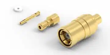
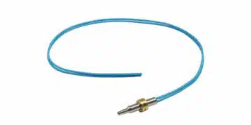
One of the first application demanding film capacitors at high operating temperature is the electric compressor. [1]Vehicles primarily use electric compressors in two ways: in E-charger systems and in air conditioning systems. The circuit design for each of these applications is similar, as is the harsh condition in which these systems must operate.
E-Charger Application
An E-charger functions as a turbocharger, but one that is driven by electronics, rather than mechanically driven by belts (often called “superchargers”) or exhaust airflow. E-chargers have particular and obvious advantages over traditional turbochargers in hybrid electric vehicles, given their significant electrical power.
The challenge for the E-charger application is that much of the electronics used to monitor and control these devices must reside in the engine compartment. Engine compartments are high heat, high humidity, high vibration – the real definition of harsh environments. Any components used must be capable of not just withstanding those harsh conditions, but also thriving in them. They must be as small as possible, but also have a long and reliable life.
Electric Compressor Design
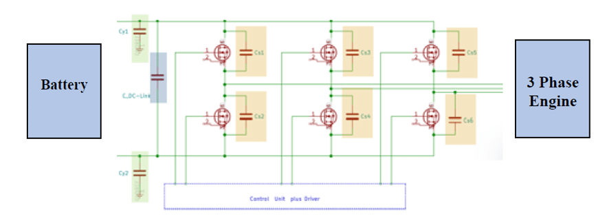
EVs and HEVs electric compressors drivers use an inverter circuit to convert a high DC voltage to an AC voltage. Fundamentally, this circuit involves an EMI/safety stage, a DC-Link capacitor, and then a MOSFET inverter stage. The trend in EV and HEV components is simplification, miniaturization, and higher power density. DC-Link capacitors are also required to work at higher temperatures, for a longer lifetime, with every new generation.
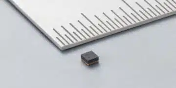
OBC (On Battery Charger)
OBC market is essential component of automotive electrification and it is growing rapidly as the demand for battery powered EV is increasing worldwide. OBC system is composed of AC/DC converter with PFC cascaded with DC/DC converter to control power delivery to the battery. Here below a typical example how can be used a resonant film capacitor in LLC resonant converters in OBC design.
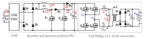
The resonance converter works on high frequency, and its temperature is rising additionally. Due to the miniaturization of OBC, the packaging size becomes smaller and it causes higher ambient temperature. Thus, for this LLC resonant converter must be developed components which has high temperature resistance.
WBG Wide Band Gap
The key factors for the electronic world designs to use WBG are greater efficiency, higher temperature, frequency of operation, and greater power density designs. Translating all those factors to the passive components needed for the final conversion system turn to the use of smaller components like capacitors and magnetics. For instance, a SiC module can perform at 25 kHz or higher vs. previous Si designs operating at the 8 to 10 kHz range, allowing the DC-Link capacitor bank to be reduced from 1,000 mF ranges, using power electrolytic and film canister solutions, dramatically to just hundreds of μF requirements, using power box film radial solutions. According to WBG producers, this switch of semiconductor technologies can bring design reduction factors up to 50%, and according to GaN Systems experts, they expect reductions of up to 3x improvement in power density using SiC and GaN in applications as On-Board Chargers.
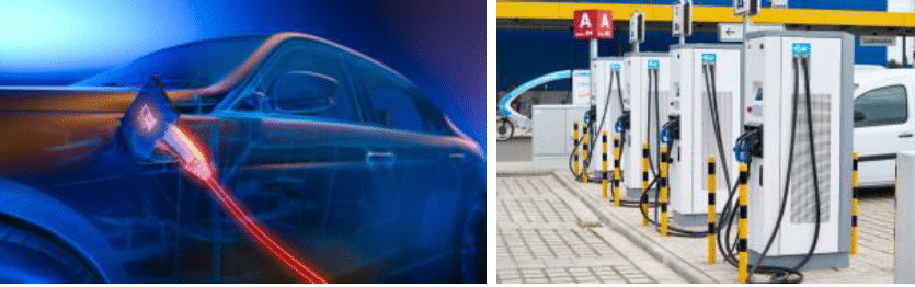
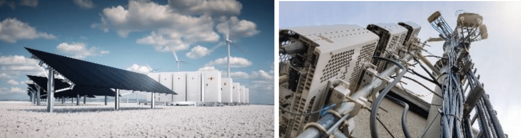
Fig.3: Electronics industries and applications benefiting from WBG solutions advantages
In addition to this impressive power density increase and efficiency gain on switching from large electrolytic and film canisters to a bank of power box film technologies for the DC-Link power bank, the film technology requires to perform under critical levels of operational conditions. The high ambient temperature and humidity conditions require the designers to compensate the capacitor top performances (e.g. ripple, voltage capability) with derating factors to maintain a reliable DC-Link solution for extended operational hours under those environmental conditions and extended lifespan.
HIGH TEMPERATURE & RESONANT FILM CAPACITORS
HIGH TEMPERATURE FILM CAPACITORS
Capacitors in BOPP (Biaxially Oriented Poly Propylene) film are widely used in the electronic and power market for its well-known main advantages as:
- high reliability
- high stability of capacitance and tgδ (dissipation factor) or ESR (Equivalent Series Resistance)
- high BDV (Break Down Voltage) characteristics able to withstand high transient and peak voltages without going into catastrophic failures as short circuit condition
- high Irms/Vrms value and therefore high working power thanks to its low ESR values
- high mechanical and vibration withstanding thanks to the flexibility and elasticity of the film dielectric
- high Performances/Cost ratio
On the contrary the standard film capacitors made in BOPP film starts to show a decreasing of its property at temperature higher than 105°C. KEMET has studied the root cause and failure mechanism of these performance decreasing to design new generation of series or subseries able to work at higher temperatures or at similar maximum temperature but with enhanced performances. In the following chapters, it will be detailed the research and design activities for new Resonant and new DC-Link Power Box capacitors family developments.
RESONANT FILM CAPACITORS
The resonant tank circuit is named LLC because it is composed of resonant inductor, resonant capacitor and magnetizing inductance of the isolation transformer. The square waveform from DC/DC switching block becomes an “almost” sinusoidal signal through the LLC tank circuit, which is transferred to the isolation transformer. The resonant Film capacitors have been required to:
- Bring high Vrms/Irms values in a frequency range up to resonance frequency. This characteristic is allowed through the usage of base film with very low Tgδ and a proper design of the film metallization with the purpose to minimize the ESR (Equivalent Series Resistance)
- Have high reliability. Film capacitors are mainly used for this characteristic in application where catastrophic failure as short circuit should be avoided. This important property is given by 2 important factors of film capacitors as flexibility and self-healing. Flexibility assures to not have cracks inside film layers and avoiding increasing of mechanical tensioning that could reduce the BDV (Break Down Voltage) in working conditions. The desired reliability is reached adding to the flexibility the self-healing property. Weak points such as pinholes, embedded foreign particles, or even micro flaws in the semi-crystalline polymer film can lead to a localized clearing of the film as the applied voltage increased. Such a clearing event results in a discharge of a portion of the stored energy, with consequent localized high temperature and pressure buildup. At the same time, the film is punctured and the thin metal layer at the defect site is rapidly vaporized and driven outwards from the breakdown site. Thus, the plasma of the breakdown arc is interrupted, and the site becomes electrically isolated. After the self-healing, the capacitor can be taken into higher an even voltage level.
- Have high capacitance and Tgδ stability.
These capacitors are used in applications where high Vrms/Irms are required as resonant & snubber ones. The required stability is obtained by a proper design of the metallization and the design of the process parameters for the components manufacturing. In these series the metallization profile is flat and quite thick to minimize the ESR value and increasing the capacitance and Tgδ stability in the lifetime. The metallization thickness is about 100-200nm - Have a high Peak current measured as dV/dt value in a range of 35-9500V/μs.
The current is easily measured by the following formula Ip=C*dV/dt. Usually these high peak current values are obtained with optimized process parameters especially during the building of the “Schoopage” layer and of the compactness phase. Wave cut technology is also used to increase the contact area and mechanical strength contact of the metallized film in the “Schoopage” layer - Capability to work either in DC and in AC application.
This characteristic is allowed thanks to the adoption of a thick aluminum metallization well protected by all enclosure materials - THB (Temperature Humidity Bias) withstanding at 85°C/85%RH for 1000h either in DC & in AC
In such test conditions the metallization oxidation of the film is the main root cause for capacitance drop and Tgδ increasing.
The corrective action adopted by KEMET are mainly focused to reduce the humidity absorption rate by internal elements with a deep analysis and relative adoption of all properly enclosure materials and film. The process has been also mainly reviewed to optimize the compactness level of the internal film elements. The main phases form winding up to the thermal treatment have been meaningfully reviewed for such purpose, impacting also on machine and equipment design.
To increase the operating temperature of the pulse series up to 125°C the following failure mechanism have been analyzed and inhibited thorough a proper design:
- Oxidation of the metallization layer. Above 105°C the Al metallization starts to become sensitive to the oxidation and for this reason KEMET has worked to reduce such failure mechanism. The main technical activities have been focused to increase the compactness level of internal film elements, protecting the metallization and reducing the humidity absorption through a proper design of all enclosure materials
- TD (Transversal Direction) shrinkage of the film. Increasing the working temperature, the film shrinkages in transversal direction with the risk of decreasing the mechanical contact versus the spraying layer. This mechanical stress could increase the Tgδ and reducing the dV/dt withstanding of the capacitors. Also the Tgδ increasing is an effect really sensitive for Pulse capacitors that are mainly designed to bring high level of Irms/ Vrms. In order to reduce the natural shrinkage of BOPP film at high temperature the process parameter is proper designed. The main tuning is related to the thermal treatment and to the compactness variables of the film capacitors.
KEMET to meet the Customer requirements of high working temperature for Resonant capacitors has developed 2 kind of series based on 2 different type of construction:
- R75H with single metalized film and a series connection variable from 1 to 3 depending on the DC/AC voltage
- R76H with double metallized film and a series connection variable from 1 to 3 depending on the DC/AC voltage
R75H
R75 H is a sub series of the standard Automotive resonant R75 series with extended operating temperature up to 125°C. R75H main features:
- Operational life at Vop (DC) > 200,000 hours at 85°C; 6,000 hours at 110°C; 2,000 hours at 125°C
- Voltage range 160 – 2000Vdc
- 1-3 series design depending of the DC&AC Voltage
- dV/dt range 35 – 9500V/μs
- AECQ200 considering a temperature range of -55 + 110°C
- THB 60°C/93%R.H. Vrdc&Vrac 1000h
- THB 85°C/85%R.H. Vrdc&Vrac 1000h
The extended operating temperature up to 125°C and the THB withstanding have been obtained thanks to:
- Improved film base material with specific optimized metallized layer
- Tailored process parameters design specific for R75 H
- Specific Epoxy resin filling
R76 H
R76 H is a sub series of the standard Automotive resonant R76 series with extended operating temperature up to 125°C. The double metallization construction with PET carrier gives the possibility to this series to maximize the dV/dt performances and reducing the dissipation factor increasing consequently the Irms withstanding. Main features:
- Operational life at Vop (DC) > 200,000 hours at 85°C; 6,000 hours at 110°C; 3,000 hours at 125°C
- Voltage range 250 – 2000Vdc
- 1-3 series design depending of the dc&ac Voltage
- dV/dt range 100 – 9500V/μs
- AECQ200 considering a full temperature range of -55 + 125°C
- THB 60°C/93%R.H. Vrdc&Vrac 1000h
- THB 85°C/85%R.H. Vrdc&Vrac 1000h
The extended operating temperature up to 125°C and THB withstanding have been obtained thanks to:
- Improved film base material with specific optimized metallized layer
- Tailored process parameters design specific for R76 H
- Specific Epoxy resin filling
R75 H – R76 H – Characteristics and Performances
In this chapter will be presented the characteristics and the performances of the 2 different series.
The list of tests and electrical characterization made on the R75H& R76H are:
- Typical ΔC/C behavior in the endurance test performed at 105°C & 125°C in DC and @ 125°C for AC
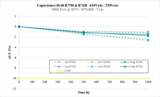
- Typical ΔC/C behavior in the THB 85°C/85%RH Vrdc & Vrac test for the series
- ΔT vs Tamb for the different series
- Irms at 100°C and at 115°C for R75H & R76H for a 47nF/1000Vdc p15
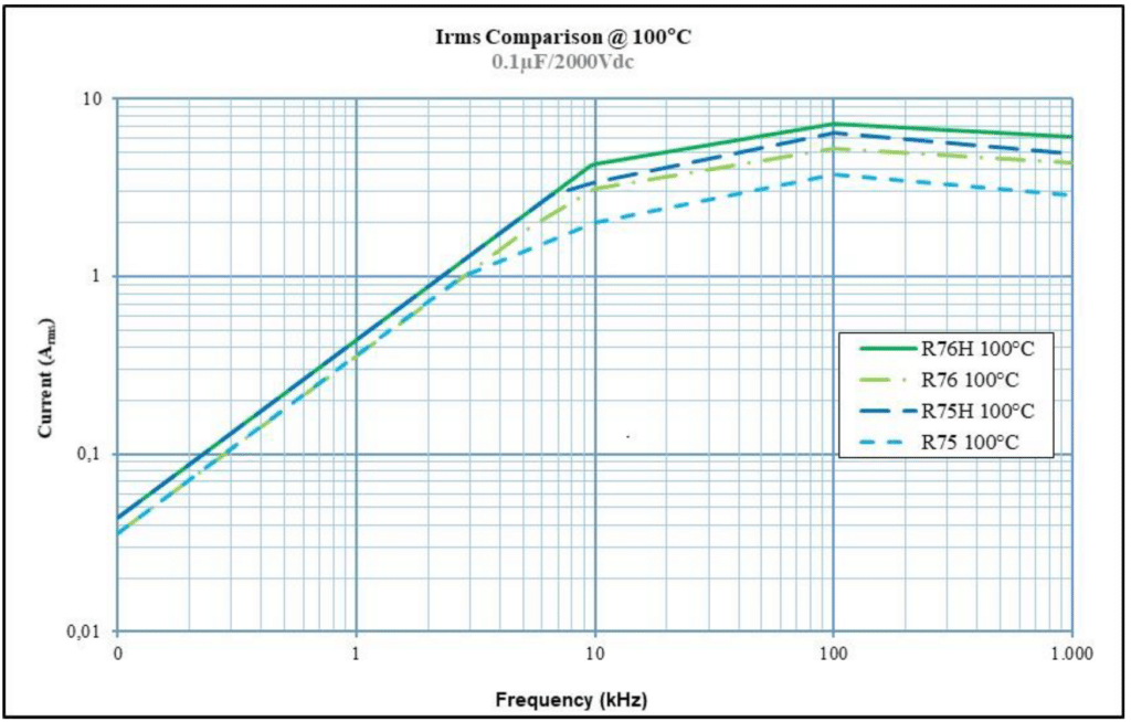
- Irms of R75H & R76H compared to R75 & R76 at 100°C for a 0,1μF/2000Vdc p27,5
Here below the different graphs for the typical behavior of the series in the endurance tests.
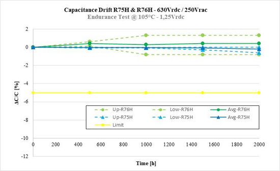
Both series shows a high level of stability in the above endurance test up to 2000h. Some capacitors show an increasing of the capacitance versus then initial value (up to about +1,5%) due to the increasing of the compactness of the internal film element for the contemporaneous presence of DC electric field and temperature applied to the film. The DC electric field applies a force in the direction to close the film layers one to the other. The temperature causes a shrinkage of the film in the biaxially directions of the film layers and therefore a slightly film thickness increasing. Both mechanical force and film thickness increasing, reduces the air content between the film layers causing a slightly increasing of the capacitance value.
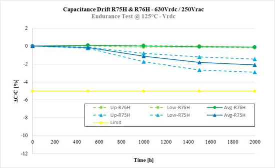
R75H is showing a slightly decreasing of the capacitance value higher than R76H series. This difference is mainly related to the different construction of the 2 series. R75H is built by a single metalized film with a PP film base material. R76H is built by a double metallized film with a PET film base material. The decreasing of the capacitance value of R75H is mainly due to the shrinkage of the film at 125°C. C = *A/d ( = dielectric constant, A = Useful Area and d = dielectric film thickness). The shrinkage decreases the useful area A and increases the film thicknesses with the consequence of the capacitance decreasing. Double metallized construction reduces the shrinkage of the film due to the double layers of metal and the shrinkage level of PET at 125°C is lower than the PP film.
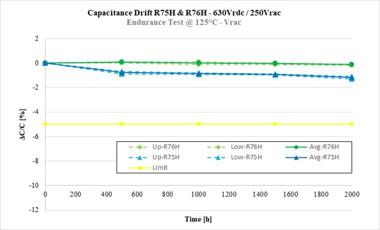
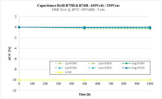
As for the previous endurance test @ 125°C at Vrdc also in Vrac the R75H shows a slightly higher decreasing of the capacitance value than R76H. Both series show high stability performances at 85°C / 85%RH Vrdc for 1000h.
At 85°C / 85%RH Vrac the capacitance decreasing is slightly higher than Vrdc for oxidation and corona effect phenomena [2],[7].
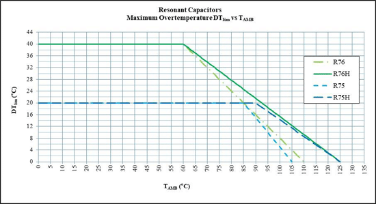
The double metallized series R76 & R76 H can allow a ΔTlim up to 40°C for ambient temperature 60°C. From Th>90°C the new single metallized series R75 H starts to show advantages than std R76. R76H @ 100°C & 100kHz is showing an Irms increasing of 39% than std R76. R75H is comparable to R76 @100°C & 100kHz. From 100kHz to 1MHz the double metallized series show an advantage because the current is still increasing with the frequency.
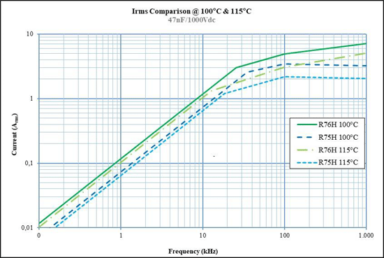
At 115°C R76 & R75 can’t work because the maximum operating temperature of such series is 105°C.
As per above graph related to a 0.1μF/2000Vdc R76H @ 100°C is confirmed an increasing of the Irms at 100kHz of 39% than std R76. For high capacitance value R75H is even higher in term of Irms than std R76.
DC-LINK POWER FILM CAPACITORS
DC-LINK POWER BOX FILM CAPACITORS
The DC-Link capacitor is present in all power converters, in the DC part of the circuit between the input and output stages. This capacitor is critical to filter the DC voltage and to store energy to provide instantaneous current to downstream circuits. The DC-Link capacitor must be able to withstand high power, high ripple currents, and a large amount of charge/discharge cycles. Furthermore, in this specific application, they must also withstand high temperatures and harsh conditions in the engine compartment of a vehicle. [1]
Traditionally, electrolytic capacitors have been the choice for power conversion applications due to their low cost per capacitance and high energy storage (i.e. capacitance) per volume. But the trend of higher ripple current and higher voltages is forcing designers to consider more film technology. The DC-Link application requires capacitor that can be able to work at high frequency with a range of working voltage up to 220V/μm able to reach temperatures up to 135°C.
Main targets for a DC-Link Film Capacitor:
- High Vrms/ Irms values in a frequency range up to resonance frequency. This characteristic is allowed through the usage of base film with very low Tgδ and a proper design of the film metallization with the purpose to have a low ESR (Equivalent Series Resistance).
- High reliability. Film capacitors are mainly used for this characteristic in application where catastrophic failure as short circuit must be avoided. As for Resonant capacitors this important property is given by the two important factors of film capacitors as flexibility and self-healing.
- High capacitance and Tgδ stability. These capacitors are used as DC link to stabilize the voltage and reducing the ripple voltage for a quite constant DC output. The decreasing of the capacitance value in the lifetime would reduce the filtering effectiveness of the circuit design. The designed stability is obtained by a proper design of the metallization and of the process parameters for the components manufacturing. The metallization profile of each film layer is tailored to maintain the right compromise between a high self-healing property, low ESR and high capacitance and Tgδ stability. One of key technical choices is the design of the metallization thickness of the active area of the film layers inside the capacitors. Increasing the metal thickness, the ESR reduces, increasing the Vrms/Irms withstanding, increasing the capacitor stability also reducing the sensitivity of the internal element to be oxidized. On the contrary the metal thickness reduction increases the self-healing property and therefore its reliability versus transient or spike voltages.
- High volume efficiency increasing the Capacitance density (with a cap density range from 0.14 nF/mm3 @ 1500Vdc/70°C to 1.37 nF/mm3 @ 500Vdc/70°C). The miniaturization of DC-Link Film capacitor is usually made increasing the Voltage for every μm of film thickness used. Such DC Links are working @ 70°C up to 220V/μm. In this way a 1500Vdc rated voltage is using a 7um instead of a 500Vdc that is using a 2,7um. The V/μm increasing is usually obtained also decreasing the metal thickness of the film (self-healing improving)
- High Peak current measured as dV/dt value (in a range of 15-100V/μs). The current is easily calculated by the following formula Ip=C*dV/dt. Usually these high peak current values are obtained with optimized process parameters especially during the building of the “Schoopage” layer and of the element compacting phase
- High humidity robustness grade. Especially in solar market but also in the Automotive the 85°C/85%R.H. with Voltage applied is nowadays became a usual requirement. In such conditions the metallization oxidation of the film is the main root cause for capacitance drop and Tgδ increasing. The corrective action adopted by KEMET are mainly focused to reduce the humidity absorption rate by internal elements with a deep analysis and relative adoption of all properly enclosure materials and film. The production process has been also mainly reviewed to optimize the compactness level of the internal film elements. The main phases form winding up to the thermal treatment have been meaningfully reviewed for such purpose.
As per the abstract of this paper, the market is currently requiring DC-Link Power Box capable to work at 125°C and for enhanced applications up to 135°C with high voltage and longer lifetime at 125°C.
The main failure mechanisms at 125°C and at 135°C are:
- IR (Insulation Resistance) decreasing of the BOPP film dielectric. IR decreasing is equivalent to the leakage current increasing, that for BOPP film starts to be meaningfully at 105°C. Above 125°C such film is not used for electronic market application due to this high leakage current and its starting of fast degradation mechanism. At about 140°C it starts melting. For applications with a maximum temperature of 125°C KEMET has selected an improved BOPP film because it assures great electrical performances and good reliability. Proper film base material is selected to maintain good BDV (Break Down Voltage) and self-healing up to 125°C from one side and maintaining good stability up to 125°C in terms of ΔC/C% and Δtgδ. The standard Polypropylene essentially loses most of its strength above 105°C therefore for applications with enhanced voltage at 125°C and a working temperature up to 135°C KEMET started to use a High Temperature Dielectric Film (HTDF). The selected HTDF increases the mechanical strength and reduces the insulation resistance in a wider temperature range up to 135°C.
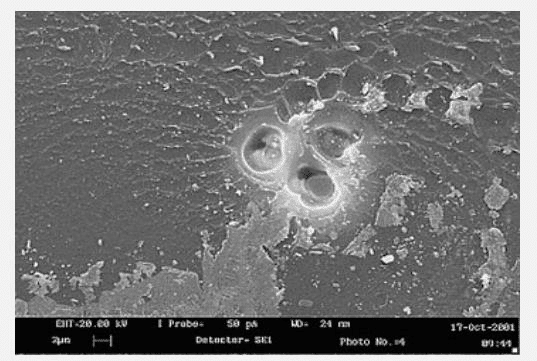
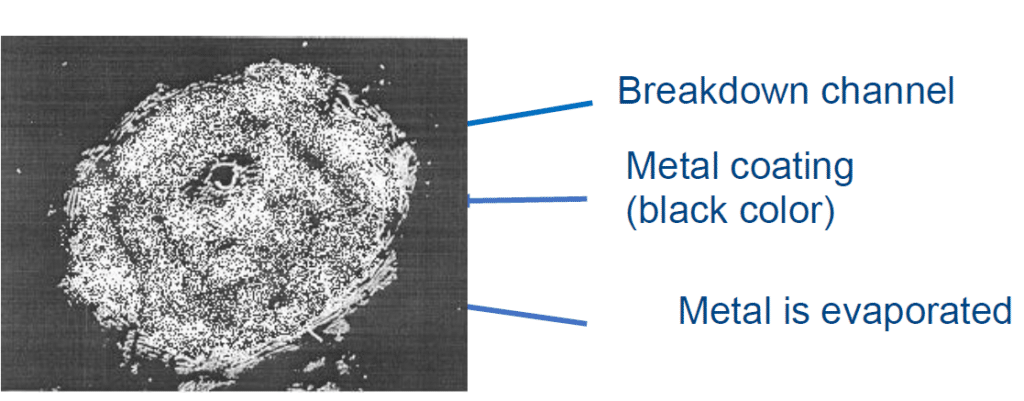
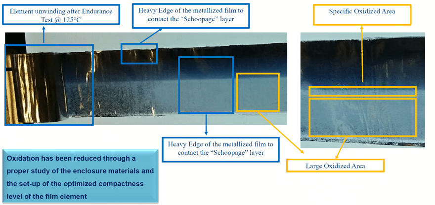
- High oxidation level of the metallization. The DC-Link capacitors to work up to 220V/μm have been designed using a very thin metal level in the range of 15-40nm. Above 105°C the thin metallization starts to become sensitive to the oxidation and for this reason KEMET has worked to reduce such failure mechanism. Here below it’s possible to see some pictures of film with different kind of oxidation after an endurance test performed @ 125°C – 0,78Vrdc. As for THB Grade achievement, the main technical activities have been focused to optimize the compactness level of internal film elements, protecting the thin metallization and reducing the humidity absorption through a proper design of all enclosure materials and capacitor assembly process. See Figure 14.
- High level of TD (Transversal Direction) shrinkage of the film. Increasing the working temperature, the film shrinkages in transversal direction with the risk of decreasing the mechanical contact versus the spraying layer. This mechanical stress could increase the Tgδ and reducing the dV/dt withstanding of the capacitors. Also the Tgδ increasing is an effect really sensitive for DC-Link power box capacitors that have to bring high Irms/ Vrms values. To reduce the natural shrinkage of BOPP or HTDF film at high temperature the process parameter is proper designed. The main tuning is related to the thermal treatment and to the compactness variables of the film capacitors.
KEMET to meet the Customer requirements of high working temperature for DC-Link power box capacitors has developed two products’ series based on two different type of dielectric film:
- C4AQ-P in BOPP (standard Biaxially Oriented Poly Propylene) with enhanced Performances at 115°C & 125°C with longer lifetime
- C4AK with HTDF able to work up to 135°C with increased V/μm at 115 & 125°C
Here below the main characteristics and performances of the new 2 series:
C4AQ-P
C4AQ-P is a sub series of the standard Automotive power box DC-Link C4AQ with enhanced Performance of Lifetime >85°C. In specific this series is designed to work 4000h @ 125°C at 100V/um. All other characteristics of the C4AQ series have been maintained as:
- operating and rated voltage @ 70°C & 85°C
- AECQ200 considering a temperature range of -55 + 105°C
- THB 40°C/93%R.H. Vrdc 1000h
- THB 60°C/95%R.H. Vrdc 1000h
- dV/dt values up to 80V/μs (Vrdc 1100Vdc) considering an operating temperature up to 125°C
The increased lifetime at 105-125°C has been obtained thanks to:
- Improved film base material
- Improved metallization design
- Tailored process parameter design specific for C4AQ-P
- Specific Epoxy resin filling
C4AK
C4AK is a new special Power box DC-Link series from KEMET able to work up to 135°C with increased lifetime and reduced derating voltage @125°C able to withstand the harsh environment up to 85°C/85%R.H. also for automotive applications. Characteristics of this new series:
- Lifetime of 4000h @ 125°C with a voltage from 125 to 145V/μm.
- Lifetime of 15000h @ 125°C with a voltage up to 100V/μm (C4AQ-P & C4AQ level)
- Same operating and rated voltage @ 70°C & 85°C than C4AQ
- AECQ200 considering a temperature range of -55 ÷ 105°C
- THB 40°C/93%R.H. Vrdc 1000h
- THB 60°C/95%R.H. Vrdc 1600h
- THB 85°C/85%R.H. Vrdc 1000h
- dV/dt values up to 40V/μs (Vrdc 700 & 900Vdc) considering an operating temperature up to 135°C
The increased V/μm at T > 85°C and the working voltage up to 135°C have been obtained thanks to:
- Implementing of new HTDF
- Improved and customized metallization design
- Tailored process parameter design specific for C4AK with increased thermal treatment for the new film used
- Specific Epoxy resin filling
C4AQ-P & C4AK – Characteristics and Performances
In this chapter the characteristics and the performances of the two new series will be compared with the standard C4AQ.
The comparison is structured considering the following schema:
- Characterization of C4AK vs C4AQ-P of ΔC/C [%] vs t [°C], Tgδ vs t [°C] and IR [Mohm] vs t [°C]
- Electrical performances of the DC-Link power box series (C4AQ vs C4AQ-P & C4AK), in particular:
- Operating voltage vs T for the different series
- Typical ΔC/C behavior in the endurance test performed at 85°C, 105°C, 125°C and the typical behavior in the endurance test of C4AK at 135°C
- ΔT vs Tamb for the different series
- Irms at 85°C & 105°C for the different series for a 14μF/900Vdc at 85°C
- Lifetime comparison of the different series considering the hot-spot temperature at 85°C, 105°C, 115°C, 125°C and 135°C only for C4AK
Here below the different graphs for the characterization of the series:
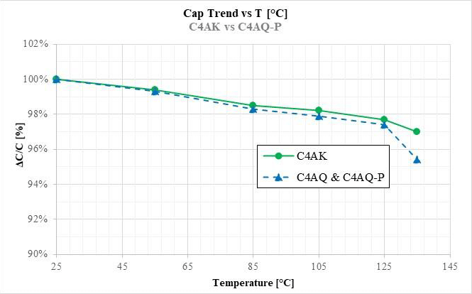
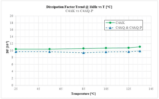
The capacitance trend versus T is showing meaningful difference of C4AK series made with the new dielectric HTDF vs the series C4AQ & C4AQ-P made with PP base @ T > 125°C. The graph on Fig 16. is showing a dissipation factor trend @ 1kHz of the C4AQ & C4AQ-P series slightly better than C4AK one. However, considering the dependence of this value vs the Rmet value of the metallization and its tolerance, these values are considered not meaningful different.
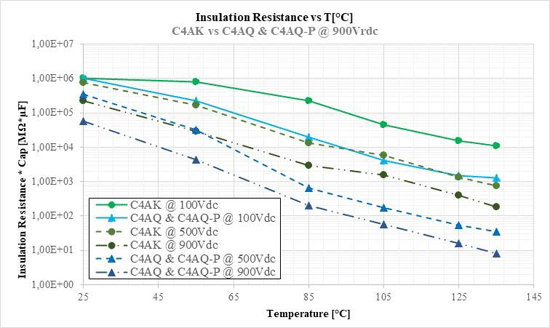
In the graph on Figure 17. is clearly visible the improvement in terms of IR vs T of the C4AK series made with the new HTDF vs the C4AQ & C4AQ-P series made with PP film. C4AK measured of IR at 900Vdc with 5um film is showing an IR higher than PP 5um at 500Vdc. The curves are related to the IR*μF [s] to plot values independently to the capacitance considered.
Such improvement it’s really a key factor of the working of C4AK at high voltage level at 125°C and of the working extension up to 135°C.
Here Below the operating voltage versus temperature of the series C4AK & C4AQ-P. The C4AQ-P has the same operating voltage than C4AQ but with an increased lifetime at high temperature conditions. For instance, @ 125°C C4AQ-P can work at the operating voltage for 4000h instead of 200h of the std C4AQ.
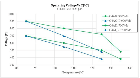
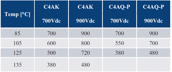
As for above graph on Fig.18 and above table Tab1. is possible to note that the C4AK can work at higher orating voltage than C4AQ-P series. In particular C4AK @ 700Vdc has an operating temperature @ 125°C (500Vdc) higher than the C4AQ-P @ 900Vdc (480Vdc). Moreover, the C4AK @ 700Vdc can be used safely in the 450Vdc automotive bus up to 125°C.
Here below the different graphs for the typical behavior of the series in the endurance tests.
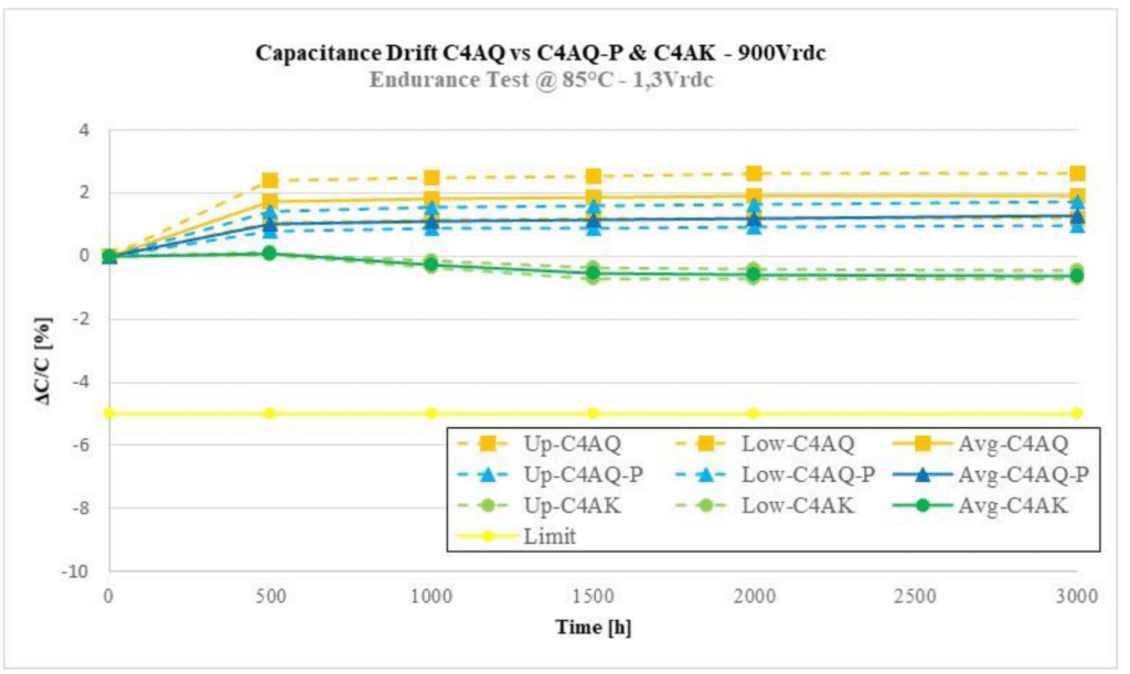
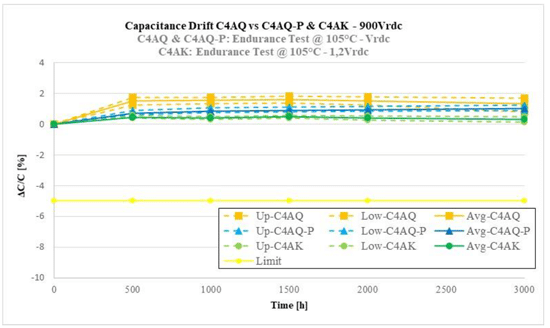
All DC-Link series show a high stability level up to 3000h @ 85°C. Both C4AQ & C4AQ-P show an increasing of the capacitance value due to the increasing of the compactness level during the endurance test for the simultaneous presence of DC high electric field and temperature as explained in the resonant capacitor session. C4AK is instead showing a decreasing of the cap value because such capacitors are more compact and more thermally stabilized than the C4AQ & C4AQ-P series.
All DC-Link series show a high stability level up to 3000h @ 105°C. In these conditions also C4AK starts showing an increasing of the capacitance value due to the increasing of the compactness level.
It’s important to underline as C4AK has been tested at a voltage level 20% higher than C4AQ & C4AQ-P series.
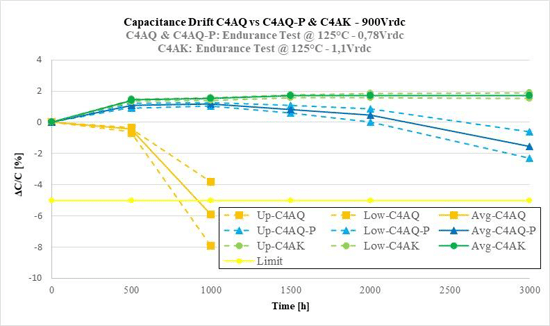
In the graph on Fig.21 it’s important to underline that C4AK has been tested @ 125°C at a voltage 40% higher than C4AQ & C4AQ-P. The endurance @ 125°C highlight the great achievements of the development of the series C4AQ-P & C4AK versus the std C4AQ. C4AQ-P with PP film increase the lifetime of 200h @ 125° of the C4AQ up to 4000h at 0,6Vrdc. C4AK can work at 125°C 0,85Vrdc for 4000h thanks to the KEMET design and the usage of the new HTDF film.
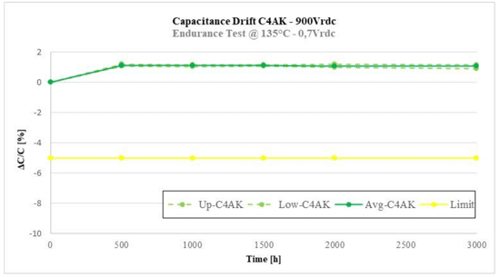
Very good stability is showed by this endurance test @ 135°C – 0,7Vrdc by C4AK – see Fig.22. Thanks to high DC electric field and 135°C applying compactness increasing is visible. In this test any meaningful oxidation or meaningful clearing is not showed.
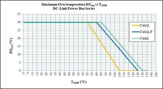
Up to a TAMB = 70°C the ΔTLIM of all 3-power box DC-Link series is = 30°C and therefore the max Irms allowed by the 3 ones is almost similar. For a TAMB > 70°C C4AQ-P & C4AK start showing higher Irms capability versus C4AQ as per following examples.
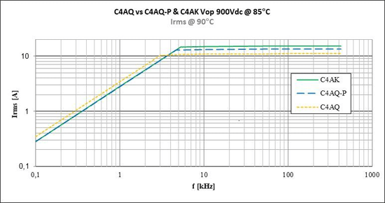
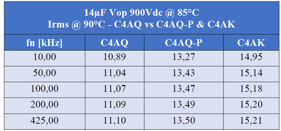
C4AQ-P is allowing almost 22% a higher Irms@90°C than std C4AQ. C4AK can withstand almost 10% higher Irms than C4AQ-P and therefore almost 35% higher Irms than C4AQ.
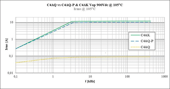
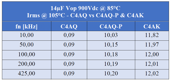
C4AQ-P is allowing almost 11 times a higher Irms@105°C than std C4AQ. C4AK can withstand almost 18% higher Irms than C4AQ-P and therefore almost 12 times higher Irms than C4AQ.
C4AQ-P & C4AK – Product Lifetime
The development activity to increase the working performances at high temperature from 115 to 135°C and also increasing the operating voltage as for C4AK series at high temperature have positively contributed to increase the maximum Irms of the series C4AQ-P & C4AK than std C4AQ at temperatures > 85°C.
Here below the different graphs for the Lifetime comparison for the different power box DC-Link series.
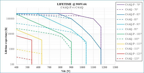
From the graph on Fig. 26 left it’s possible to underline the following improvements and characteristics of the series C4AQ-P vs C4AQ:
- @70°C the lifetime is almost the same between the 2 series except for the increasing up to 220kh for C4AQ-P at Vrdc
- @85°C the lifetime is almost the same between the 2 series except for the increasing up to 220kh for C4AQ-P at about 0,85Vrdc
- @95°C & 105°C C4AQ-P has increased meaningfully the lifetime versus C4AQ
- @115°C the lifetime of C4AQ-P at 0,7Vrdc has been increased from 500h to 4000h
- @125°C the lifetime of C4AQ-P at 0,6Vrdc has been increased from 200h to 4000h
From the graph on Fig.27 right it’s possible to underline the following improvements and characteristics of the series C4AK vs C4AQ-P:
- @70°C & 85°C the lifetime is the same for C4AQ-P & C4AK
- @95 & 105°C C4AK has increased meaningfully the lifetime and operating voltage versus C4AQ-P
- @125°C the lifetime of C4AK at 0,6Vrdc has been increased from 4000h to 15000h. Moreover, the maximum voltage at 125°C has been increased from 0,6Vrdc to 0,8Vrdc
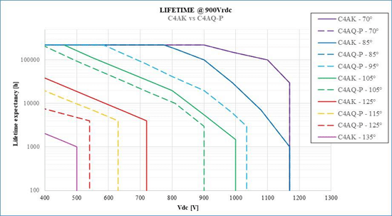
All lifetime showed in the previous 2 graphs are a result of focused research and design activity and long endurance test with the aim to maximize its for the power box DC-Link series. Such activity can not consider just the Arrhenius and voltage formula, but it should consider all the failure root causes as clearing effects, oxidation at high temperature and aging with the combination of voltage and temperature. The sum of all different failures considered explains the fact that the curves are not simply a line in a semi-logarithmic graph, but they are a more complex curve. Moreover, all the lifetime curves are saturated at 220kh only because there is not available data to support higher number of hours.
CONCLUSION
CONCLUSION
The new series have been developed to overachieve the Customers’ requirements anticipating the future market needs with a very high focus on the temperature performances. Only few years ago, it was considered not possible and safe to have series in Polypropylene dielectric film working continuously at 125°C. It’s well known the decreasing of the IR and the exponential increasing of the shrinkage of such film at temperature above 105°C. During these years KEMET Advanced R&D Department worked deeply on the root causes analysis for the failures observed during test performed at high temperature. This activity allowed to determine the real weight of each cause related to process and materials and therefore working in an effective way for the improvement of the new series.
With such new series KEMET has merged the requirement to increase the working temperature with general new trend as:
- Withstanding the THB requirement at 85°C/85%RH with Vr applied
- Increasing the dV/dt withstanding as required by the implementing of the new SiC & GaN technology
Moreover, the launching of the new C4AK products made with the new HTDF (High Temperature Dielectric Film) represents a first step of new generation of series able to work in the new advanced applications.
REFERENCES
[1] C4AK Application Note, KEMET
[2] M Michelazzi,E Boni,D Montanari, “RFI X2 capacitors for high humidity environment”, CARTS International, 2014
[3] Luca Caliari, Paola Bettacchi, Evangelista Boni, Davide Montanari, Arrigo Gamberini, Luigi Barbieri, Francesco Bergamaschi, “KEMET film capacitors for high temperature, high voltage and high current”, CARTS International, 2013
[4] J.H. Tortai, A. Denat, N. Bonifaci, “Self-healing of capacitors with metallized film technology: experimental observations and theoretical model”, J. Electrost., vol.53, pp.159–169, August 2001
[5] H. Li, P. Lewin, J. C. Fothergill. “Aging mechanisms of X2 metallized film capacitors in a high temperature and humidity environment.” IEEE International Conference on Dielectrics, pp.804-807, July 2016
[6] Q. Chen et al., “Moisture Ingress of Metallized Film Capacitor under High Temperature and Different Humidity Condition”, IEEE Conference on Electrical Insulation and Dielectric Phenomena – Cancun – Mexico, pp.422-425, 2018
[7] R.J. Van Brunt., “Physics and chemistry of partial discharge and corona. Recent advances and future challenges”, Dielectrics and Electrical Insulation, IEEE Transactions on, 1(5): 761-784, 1994