


This article explains basics of ESR and ripple current parameters of differences capacitor technologies as a guideline for capacitor selection for your application. The capacitor guidelines are demonstrated in two examples of DC-link capacitors and resonant / snubber capacitor selection.
The paper was presented by Alexander Nebel, Field Application Engineer at KEMET YAGEO Group at the 4th PCNS 10-14th September 2023, Sønderborg, Denmark as paper No. 5.3.
Introduction
“To find the right capacitor you just need to know Capacitance and Voltage!”
Unfortunately, this is not the full truth. It might be a sufficient statement for some DC current applications, but certainly not for AC applications.
Beside those two important electrical values, for any AC application, regardless of the frequency and the shape of the curve, also the maximum ripple current of the capacitor must be considered. Nevertheless, the maximum ripple current rating is not a constant, it depends on the application frequency and the ambient temperature. This is the reason, why the maximum ripple current cannot be stated easily in the datasheet.
According to EIA-809, the ripple current can be calculated with:
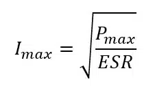
Pmax is the maximum Power rating of the capacitor and the ESR is the equivalent series resistance of the capacitor which depends on the frequency and the temperature.
Therefore, the ripple current is depending on the temperature and the frequency. Suppliers specify the maximum ripple current capability at different temperatures or frequencies and at different temperature rises. This is also the reason why products of different suppliers and different product series cannot be compared easily to each other.
If the ripple current exceeds the specifications, it might have an impact on the capacitor’s behavior. A power loss generates self-heating of the capacitor. Depending on the capacitor technology this can lead to reduction of lifetime or in worst case the capacitor can fail.
A capacitor like any passive component should never be used outside its specification.
To determine the ripple current limits of a capacitor, it is important to understand what influences the ripple current. One factor is the thermal resistance of the capacitor. The thermal resistance Rth is depending on the construction method like leads, contacts, electrodes, the product size and the cooling capability of the case and the dielectric.
Consequently, the used capacitor technology is the first main factor to consider when choosing the best fitting solution. Each capacitor technology has different construction and has therefore different ripple current capability behavior. Especially for Film Capacitors and Aluminium Electrolytic Capacitors, the self-heating is an important topic as too high temperatures may decrease the maximum lifetime.
It is important to understand that any current creates self-heating of the capacitor which is calculated by:
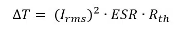
The ESR of the capacitor and the thermal resistance Rth of the capacitor have an impact, but the Irms is the main factor. It is important to consider, that besides the component characteristics also the ambient temperature, PCB characteristics, circuit design, pads, trace thickness, etc. have an influence on thermal behaviour of the component.
Key Capacitor Technologies ESR and Ripple Current Benchmark
Ceramic Capacitors
Multilayer Ceramic Capacitors are non-polar and have a very simple construction where the main part is the dielectric ceramic material with electrode layers inside. The body is the ceramic material without any additional elements such as housing, pins or resin.
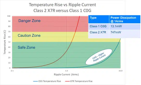
This simple construction can handle high temperatures. Nevertheless, for resonant applications like WPT or LLC, MLCCs heat up and the designer may experience overheating when not properly designing the network. Therefore, we do recommend a safe zone for temperature rise which is minimum 20C above ambient
The thermal resistance changes when using different class dielectrics as well as the DC-Bias occurs for class II and class III. Figure 1. shows consequences for temperature rise versus ripple current ratings of class I. and class II. ceramic MLCC capacitors.
Aluminium Electrolytic Capacitors
Aluminium Electrolytic capacitors are polar and thus have lower ripple current capability. Depending on the configuration of capacitor considering the used electrolyte and construction of the capacitor, Rth, ∆T and ESR vary from technology and series.
Typically, and in the past most used was a wet electrolyte. Aluminium Electrolytic capacitors have some challenges to be considered regarding higher temperatures. The latest technology is to use a Polymer instead a wet electrolyte or a combination of both: a Polymer Hybrid type.
Using polymer or polymer hybrid instead of wet electrolyte reduces the ESR of the Aluminium Capacitor over frequency and over temperature. Thus, the self-heating of the component is reduced up to ~50% and makes them ideal for higher ripple current application.
Film Capacitors
Film Capacitors are available in two different construction types: Either in metalized Film technology where the Film is the dielectric, or a combination of a Film as dielectric and two additional Aluminium Foils as Electrodes. The main reason for the usage of Film technology is the higher current capability. Nevertheless, the level of ripple current capability depends on the used film material (PP, PET, paper etc..).
The construction of Film capacitors with plastic box, film, foil, resin influences the self-heating of the capacitor.
Tantalum Capacitors
Tantalum Capacitors are polarized ultra-stable small size SMD products and have a good ripple current capability. The new Polymer Tantalum technology is having better properties than the older MnO2 technology. Tantalum Capacitors with low ESR values down to 4mΩ enable ripple currents of up to 8A per part. Limitation: low voltage up to 75V.
Example 1: DC-Link Capacitor Selection Solution
DC Link Applications need capacitors to balance instantaneous power variations between input and output sources to minimizes load changes. Due to the high ripple currents of the switching circuit, the DC Link Capacitor needs to withstand high ripple currents and a long lifetime.
In the following example, the best DC Link capacitor should be found. The requirements are:
- Capacitance: min 800uF
- Voltage: min 650VDC
- Ambient temperature: 80-85°C
- Lifetime: min. 40k hours
- AEC-Q200 qualified
For this application Tantalum Technology would not fit as the maximum voltage exceeds the typical available value. Also, the use of ceramic capacitor technology would mean to put a huge number of devices in parallel and series.
The first approach would be to use Film or Electrolytic Capacitor Technology.
In Film Technology, the metalized polypropylene C4AQ series is a good choice for Automotive Applications. The C4AQJEW6130M3BJ has a maximum capacitance of 130µF at 700VDC. To reach the required capacitance of min. 800µF the total number of 7 capacitors in parallel are needed (7 x 130µF = 820µF). The maximum ripple current with Film solution would be 42,9Arms.
In Aluminium Electrolytic Technology, the Snap-In ALA8D series is recommended for Automotive Applications. The ALA8DC821EF400 has a capacitance of 820µF at 400V. To reach the required voltage of min 650VDC 4 capacitors (2 in series and 2 parallel) are needed. The maximum ripple current with Aluminium Electrolytic solution would be 7,81Arms.
The calculated lifetime of the Aluminium Electrolytic solution would be higher, the price is slightly lower, and the recommended board space is much lower. Nevertheless, the total Ripple Current capability is much lower.
As conclusion, the best choice depends extremely on the application requirement.
Example 2: Resonant / Snubber Capacitor Selection
In resonance circuits capacitors (and/or a resistors) are needed in parallel to the semiconductor to damp dangerous voltage spikes on semiconductor switches. The highest efficiency is achieved at resonance. Therefore, a perfect matching resonant capacitor is needed.
If placed across semiconductor devices for protection and to improve performance, it is called a snubber capacitor.
The typical requirements for resonant capacitors are low ESR and high ripple current capability per capacitance at the used frequency. Also, they need to handle high dv/dt and to be stable over the full application temperature range, especially at high temperatures. Additional typical requirements include stable operation over voltage and over lifetime.
In the next example, the best resonant capacitor should be found. The requirements are:
- Capacitance: 60 – 70nF
- Voltage: min 2000VDC
- Current and Voltage: 15Arms and 310Vrms at 75kHz
- ESR: max. 15mΩ at 75kHz
- dV/dT: 5V/µs
- Ambient temperature: 85°C
- Lifetime: min. 40k hours
- AEC-Q200 qualified
For this application Tantalum Technology would also not fit as the maximum voltage exceeds the typical available value.
Aluminium Electrolytic Technology does not offer high current values as required in this example – several Capacitors in a bank would be needed.
Therefore, the first approach would be to use Film or Ceramic Capacitor Technology.
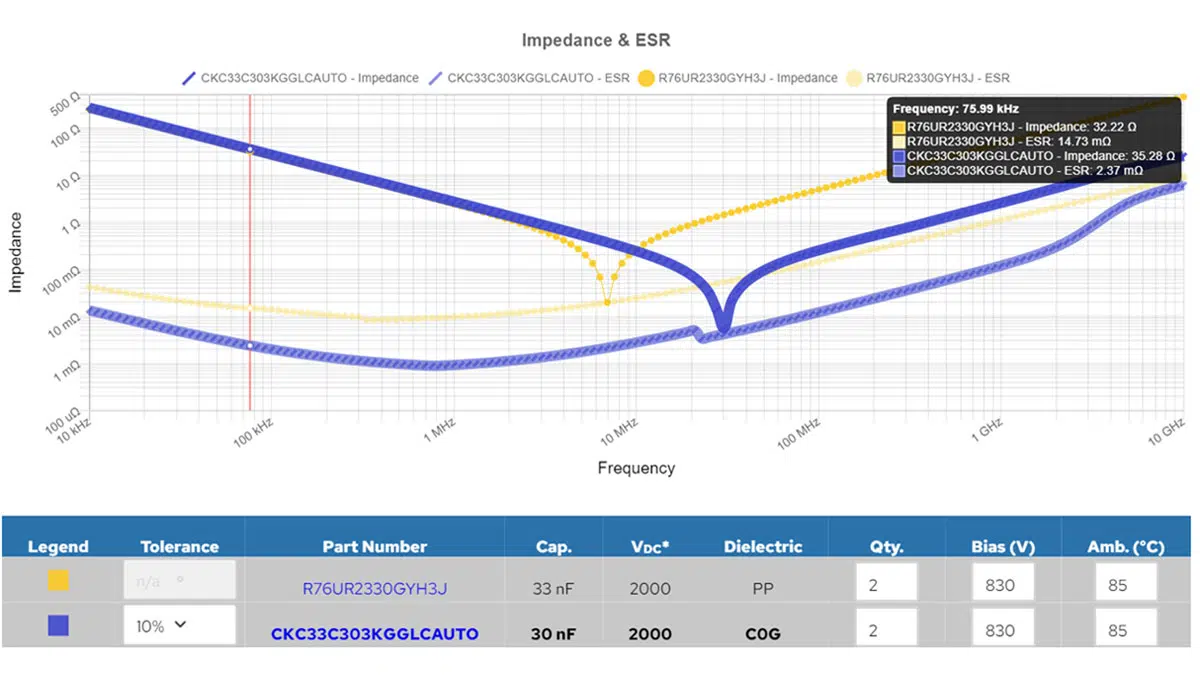
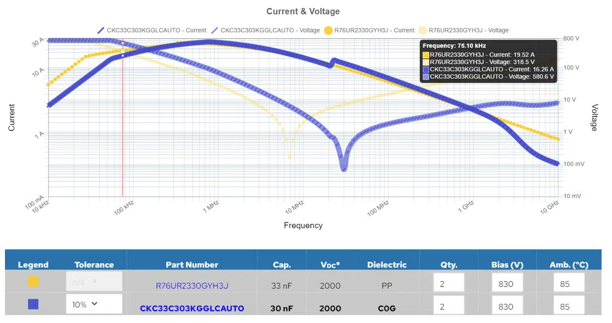
The first-to-market KONNEKT KC Link Ceramic Class 1 C0G solution is the smallest solution in SMD technology which is the best idea when space saving is recommended. Available with 2000VDC is a 30nF item which also requires 2 capacitors in parallel to reach the required 60nF. The maximum Ripple Current per Capacitor is 8.2Arms.
In Film Technology the metalized polypropylene R76 series can be chosen. The R76UR2330GYH3J offers maximum value of 2000VDC / 700VAC and 33nF. To reach the value of 60µF to 70µF two capacitors in parallel are needed. Each Capacitor has a maximum ripple current of 9.8Arms and slightly higher than the solution with Ceramic Capacitors.
Using the K-SIM Online as shown in Figure 2. and 3. allows to compare both capacitors to see the advantages:
Summary – Choosing the Best-Fit Capacitor Technology
Capacitor selection for high ripple current application should consider different aspects of the application and the technologies.
In two random examples we have seen that not one single solution is the one and only and that depending on the application’s needs more than one solution might fit.
- MLCC technology offers high capacitance and very high ripple current per volume in a small flat design at also high frequencies. The small size limits the total capacitance of the single item, so it might be an option to combine multiple MLCCs together to a bank of capacitors.
- Tantalum Capacitor Technology has a very good ripple current capability by offering high capacitance per volume, on the other hand the maximum voltage range is limited.
- Aluminium Electrolytic Capacitor technology offers the highest possible capacitance range with an acceptable ripple current capability. Using Polymer or Polymer Hybrid technologies offer higher ripple currents at also higher cost per item.
- Film capacitors is the best choice regarding high ripple currents at limited frequency range and also the cost should be taken into consideration.
Besides placing multiple capacitors on the board to increase maximum capacitance, also a mix of Tantalum Polymer and MLCCs, Aluminium and Film capacitors, or Aluminium and MLCCs is possible.
Below Table 1. compares the four capacitor technologies with features and benefits and the maximum available values at YAGEO Group as a capacitor selection guidelines.
| Parameter | Film Capacitors | Aluminum Capacitors | MLCC Ceramic Capacitors | Tantalum Capacitors |
|---|---|---|---|---|
| Max. capacitance per piece | ~4500uF (C44U-M) | 1300000uF (ALS7x) | 100uF | 2000uF (HRA), 1500 (T520) |
| Max. Voltage per piece | ~3000VDC | 630VDC | 10000VDC | 100VDC (60VDC usage from 75V) |
| Max Temperature | 135°C (in some cases up to 150°C) | 165°C | 230°C | 230°C |
| Max. Capacitance per volume | ~0.003uF/mm³ (R60) | 0.97uF/mm³ (ALS7x) | 12.2uF/mm³ (C1206C107M9PACTU 0.019uF/mm³ if class I (U2J)) | 18uF/mm³ (T520) |
| Polarization | Non-polarized | Polarized | Non-polarized | Polarized |
| Max. RMS Ripple current per piece | 100Arms @40°C and 10kHz (C44U-M) | 44Arms@70°C and 100kHz (PHA226) | 16.7A@100kHz, 33.9A@1MHz (C0G) (C2225C124KBGAC) | 12A@25°C and 100kHz (KSIM) (T528Z477K2R5ATE006) |
| Max. Ripple Current per volume | 0.012A/mm³ @85°C and 100kHz (R75) | 0.005A/mm³ @70°C and 100kHz (PHA226) | 0.226A/mm³@100kHz 0.601/mm³@1MHz (C1210C333KBGAC) | 0.24A/mm³@ 25°C 100kHz |
Conclusion
The best-fit capacitor selection requires ideally to consider all technologies and to compare each solution regarding ESR, maximum current, number of pieces, needed space on the PCB and the costs of the final solution.
YAGEOs K-SIM simulation tools are on a high level of fidelity that effectively assist designers to evaluate the component behaviour and the features of the individual capacitor technology at various operating conditions and thus assist with the selection of best fit capacitor technology for their specific application conditions.
The one who takes some time to find the best solution will ideally save money and space, which are the most important things to lead the own project to success.


