Passive Components Blog
No Result
View All Result
  • Home
  • NewsFilter
    • All
    • Aerospace & Defence
    • Antenna
    • Applications
    • Automotive
    • Capacitors
    • Circuit Protection Devices
    • electro-mechanical news
    • Filters
    • Fuses
    • Inductors
    • Industrial
    • Integrated Passives
    • inter-connect news
    • Market & Supply Chain
    • Market Insights
    • Medical
    • Modelling and Simulation
    • New Materials & Supply
    • New Technologies
    • Non-linear Passives
    • Oscillators
    • Passive Sensors News
    • Resistors
    • RF & Microwave
    • Telecommunication
    • Weekly Digest

    Circuit Protection Technology Annual Dossier

    ESA SPCD 26 Registration Open

    Capacitances of Nonlinear MLCCs: What Datasheets Don’t Tell You

    Stackpole Releases Automotive Wide‑Termination Resistors

    How a Digital Structural Twin Can Predict Tantalum Capacitor Reliability

    SCHURTER Buys Biaodi to Boost High-Voltage Protection Portfolio

    Binder Hybrid Connector Simplifies One Cable Automation

    Tapped Inductor Buck Converter Fundamentals

    TAIYO YUDEN Releases Mini Metal Power Inductors

    Trending Tags

    • Ripple Current
    • RF
    • Leakage Current
    • Tantalum vs Ceramic
    • Snubber
    • Low ESR
    • Feedthrough
    • Derating
    • Dielectric Constant
    • New Products
    • Market Reports
  • VideoFilter
    • All
    • Antenna videos
    • Capacitor videos
    • Circuit Protection Video
    • Filter videos
    • Fuse videos
    • Inductor videos
    • Inter-Connect Video
    • Non-linear passives videos
    • Oscillator videos
    • Passive sensors videos
    • Resistor videos

    Capacitances of Nonlinear MLCCs: What Datasheets Don’t Tell You

    Tapped Inductor Buck Converter Fundamentals

    Planar vs Conventional Transformer: When it Make Sense

    Modeling Fringing Field Losses in Inductors & Transformers

    Why Power Inductors Use a Ferrite Core With an Air Gap

    Transformer-Based Power-Line Harvester Magnetic Design

    Thermal Modeling of Magnetics

    Standard vs Planar LLC transformers Comparison for Battery Chargers

    How Modern Tools Model Magnetic Components for Power Electronics

    Trending Tags

    • Capacitors explained
    • Inductors explained
    • Resistors explained
    • Filters explained
    • Application Video Guidelines
    • EMC
    • New Products
    • Ripple Current
    • Simulation
    • Tantalum vs Ceramic
  • Knowledge Blog
  • DossiersNew
  • Suppliers
    • Who is Who
  • PCNS
    • PCNS 2025
    • PCNS 2023
    • PCNS 2021
    • PCNS 2019
    • PCNS 2017
  • Events
No Result
View All Result
Passive Components Blog
No Result
View All Result

One Turn Inductors Explained

19.3.2021
Reading Time: 4 mins read
A A

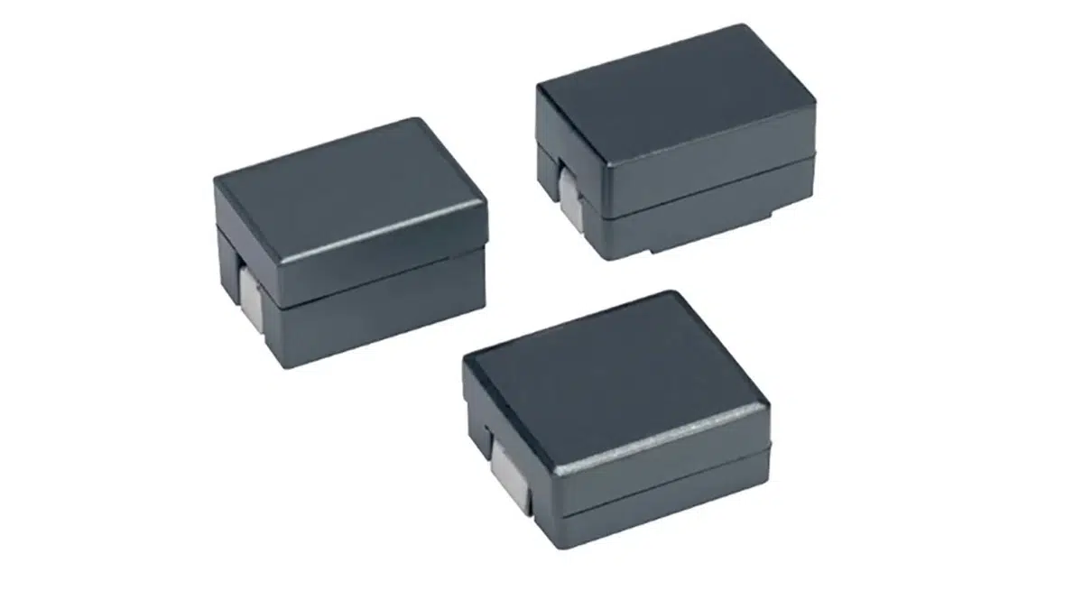
Flat wire, “one turn” inductor construction design, enables high efficiency at large currents ideal for high switching frequency applications. Kemet blog explained its basic construction and features.

Inductor Basics

Engineers know this like they know that capacitors are parallel plates, that inductors are coils of wire. That notion is beat into our heads from the early days of circuits 1. The world was so simple back then, current flowed in one direction, wires were perfect conductors, and capacitors held charge forever. Inductors store energy via a built-up magnetic field. As current flows through the coil of wire a magnetic field is created and sustained by the core material around which that coil is wrapped. When that magnetic field collapses it produces a current in the coil of wire. Fundamentally, an inductor is the dual of a capacitor. Where a capacitor is resistant to changes in voltage, an inductor is resistant to changes in current.

RelatedPosts

Circuit Protection Technology Annual Dossier

ESA SPCD 26 Registration Open

Capacitances of Nonlinear MLCCs: What Datasheets Don’t Tell You

The One Turn Inductor

Inductors don’t always have to be tightly packed coils of wire. Yes, the number of turns is one of the factors that give rise to the overall inductance. According to the equation below, it is a squared factor and therefore a major one.

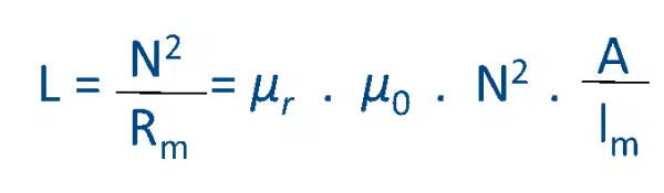
But it isn’t the only factor. The relative permeability of the core, which is determined by the material composition of the core itself, is another factor. It is possible to recover some of the inductance lost by reducing the number of turns by improving the permeability of the core by selection of inductors with high permeability ferrite core material.

One turn inductor construction; credit Kemet Electronics

It’s All About DCR and Loss

What’s so great about a one-turn inductor? OK, so no matter how great your core material is, you won’t recover all the inductance by going to one turn. But you don’t always need a ton of inductance. Especially as switching frequencies increase, you need less and less inductance. Still, turns come at a cost. One of the biggest components of loss in an inductor is the DC copper loss. If you look at the equation of resistance of a wire:

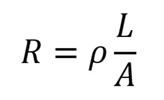
The total resistance is equal to the resistivity, ρ, which is a material parameter multiplied by the length of wire, L, divided by the cross-sectional area, A. That means that if you wanna reduce the loss of your conductor you can make it shorter or fatter (or of a different material). We’re all kinda stuck with copper for many reasons, so the resistivity is what it is. And if you make the wire fatter you increase the overall size of your component, which no one wants. So, you’re left with making it shorter.

The reduction of DCR is necessary to reduce loss. But what’s so bad about loss? Well, that power loss must go somewhere and in electronics it generally becomes heat. Unchecked heat is bad for other components and can be unsafe.

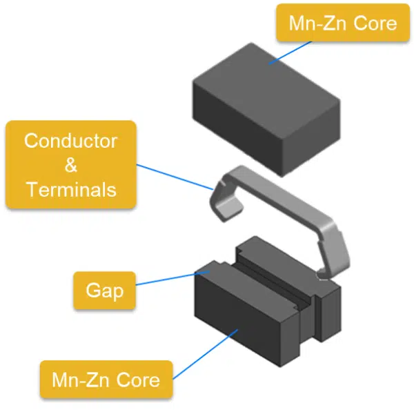
One last benefit of these assembled inductors is that the inductance can be tightly controlled by adjusting the gap size between the two clamshells. That results in inductors that can be finely tuned to ensure maximum power delivery at their operating frequency.

Focus Applications of One Turn Inductors

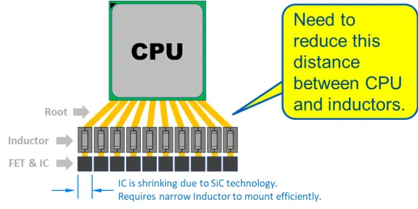
The inexorable march of electronics is generally one that goes to a higher power while shrinking in size. That is the reason why one turn large current power inductor has been developed. The one-turn design enables high current operation while reducing losses and size. More inductors and more voltage rails can be packed in a tighter space.

One turn inductors narrow chip design benefits application example; credit Kemet Electronics

Related

Source: Kemet Electronics

Recent Posts

ESA SPCD 26 Registration Open

15.5.2026
6

Capacitances of Nonlinear MLCCs: What Datasheets Don’t Tell You

14.5.2026
43

How a Digital Structural Twin Can Predict Tantalum Capacitor Reliability

14.5.2026
39

Tapped Inductor Buck Converter Fundamentals

13.5.2026
27

TAIYO YUDEN Releases Mini Metal Power Inductors

13.5.2026
28

Molecular Memristor Shows Record 145 kH Emergent Inductance

12.5.2026
31

Planar vs Conventional Transformer: When it Make Sense

11.5.2026
57

High-Crystallinity Nanocrystalline Composites for MHz Chip Inductors

7.5.2026
66

Würth Elektronik Introduces Compact Flat-wire SMT Power Inductors for Automotive

5.5.2026
56

Upcoming Events

May 19
16:00 - 17:00 CEST

Designing Qi2 Wireless Power Systems: Practical Development and EMC Optimization

Jun 2
16:00 - 17:00 CEST

Calculation, Simulation and Measurement of 800V EMC Filters

Jun 16
16:00 - 17:00 CEST

EMC with EMC – EMC‑compliant design with electromechanical connectors

View Calendar

Popular Posts

  • Buck Converter Design and Calculation

    0 shares
    Share 0 Tweet 0
  • Boost Converter Design and Calculation

    0 shares
    Share 0 Tweet 0
  • Flyback Converter Design and Calculation

    0 shares
    Share 0 Tweet 0
  • LLC Resonant Converter Design and Calculation

    0 shares
    Share 0 Tweet 0
  • MLCC and Ceramic Capacitors

    0 shares
    Share 0 Tweet 0
  • Dual Active Bridge (DAB) Topology

    0 shares
    Share 0 Tweet 0
  • Capacitor Charging and Discharging

    0 shares
    Share 0 Tweet 0
  • What Electronics Engineer Needs to Know About Passive Low Pass Filters

    0 shares
    Share 0 Tweet 0
  • Ripple Current and its Effects on the Performance of Capacitors

    3 shares
    Share 3 Tweet 0
  • MLCC Case Sizes Standards Explained

    0 shares
    Share 0 Tweet 0

Newsletter Subscription


Passive Components Blog

© EPCI - Leading Passive Components Educational and Information Site

  • Home
  • Privacy Policy
  • EPCI Membership & Advertisement
  • About

No Result
View All Result
  • Home
  • Knowledge Blog
  • PCNS

© EPCI - Leading Passive Components Educational and Information Site

This website uses cookies. By continuing to use this website you are giving consent to cookies being used. Visit our Privacy and Cookie Policy.
Go to mobile version