Passive Components Blog
No Result
View All Result
  • Home
  • NewsFilter
    • All
    • Aerospace & Defence
    • Antenna
    • Applications
    • Automotive
    • Capacitors
    • Circuit Protection Devices
    • electro-mechanical news
    • Filters
    • Fuses
    • Inductors
    • Industrial
    • Integrated Passives
    • inter-connect news
    • Market & Supply Chain
    • Market Insights
    • Medical
    • Modelling and Simulation
    • New Materials & Supply
    • New Technologies
    • Non-linear Passives
    • Oscillators
    • Passive Sensors News
    • Resistors
    • RF & Microwave
    • Telecommunication
    • Weekly Digest

    Designing 800 V DC EMC Filters: Calculation, Simulation and Measurement

    TDK Releases DC-link Film Capacitors with Ultra-low Inductance for SiC Power Converters

    Murata Introduces World First 2.2uF 100V Soft‑Term MLCC in 0805 Size for Automotive

    Murata and Xona Partner on LEO Satellite Navigation for Industrial Applications

    Bourns Offers Custom Magnetics for 3‑Phase Flying Capacitor Inverters

    YAGEO Releases Cost Efficient Pt‑RTD Sensors with Ni wires

    Nvidia Vera Rubin: Why One AI Rack Needs So Many More MLCC Capacitors

    Stackpole Introduces 1400A Busbar Shunt Resistors

    Tecate Unveils High‑temp 105C Supercapacitors for Harsh‑Environment Designs

    Trending Tags

    • Ripple Current
    • RF
    • Leakage Current
    • Tantalum vs Ceramic
    • Snubber
    • Low ESR
    • Feedthrough
    • Derating
    • Dielectric Constant
    • New Products
    • Market Reports
  • VideoFilter
    • All
    • Antenna videos
    • Capacitor videos
    • Circuit Protection Video
    • Filter videos
    • Fuse videos
    • Inductor videos
    • Inter-Connect Video
    • Non-linear passives videos
    • Oscillator videos
    • Passive sensors videos
    • Resistor videos

    Designing 800 V DC EMC Filters: Calculation, Simulation and Measurement

    Current Sense Transformer Datasheet and Design‑in Guide

    Designing a USB Type‑C Flyback Planar Transformer with Frenetic’s Planar Tool

    Magnetics Design in High‑Frequency GaN Converters

    Qi2 Wireless Charging: Inductors, Capacitors and EMC Filters

    Two‑capacitor paradox explained for engineers

    Capacitances of Nonlinear MLCCs: What Datasheets Don’t Tell You

    Tapped Inductor Buck Converter Fundamentals

    Planar vs Conventional Transformer: When it Make Sense

    Trending Tags

    • Capacitors explained
    • Inductors explained
    • Resistors explained
    • Filters explained
    • Application Video Guidelines
    • EMC
    • New Products
    • Ripple Current
    • Simulation
    • Tantalum vs Ceramic
  • Knowledge Blog
  • DossiersNew
  • Suppliers
    • Who is Who
  • PCNS
    • PCNS 2025
    • PCNS 2023
    • PCNS 2021
    • PCNS 2019
    • PCNS 2017
  • Events
No Result
View All Result
Passive Components Blog
No Result
View All Result

Würth Elektronik Ads Max Voltage Specification of its Mold Inductors Based on New Testing Procedure

17.7.2024
Reading Time: 3 mins read
A A

Würth Elektronik has developed a new testing procedure for determining the maximum operating voltage of molded inductors.

The manufacturer of electronic and electromechanical components introduces developers to the electrical property of dielectric strength and what happens if it is exceeded in an application which is described in Application Note 126 (www.we-online.com/ANP126).

RelatedPosts

Designing 800 V DC EMC Filters: Calculation, Simulation and Measurement

Qi2 Wireless Charging: Inductors, Capacitors and EMC Filters

Würth Elektronik Presents New Bidirectional Digital Isolators

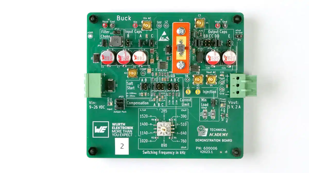
The molded inductors from the Power Magnetics product portfolio (e. g., WE-MAPI, WE-XHMI, WE-LHMI) are now successively supplemented with the value of the maximum operating voltage Vop as a new parameter in the specifications.

Based on the new testing procedure, Würth Elektronik defines the maximum operating voltage Vop in its data sheets. This represents the voltage at which an inductor can be operated continuously in the application without impairing performance, risking damage or overheating the inductor. The operating voltage is therefore a limit value for the input voltage, up to which the inductor can be used reliably in an application without irreversible damage.

The new product characteristic in the data sheet clearly indicates the maximum operating voltage of the inductor in the application; Image source: Würth Elektronik

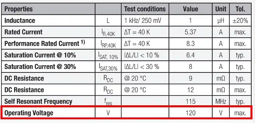
The test concept examines the behavior of inductors up to their voltage limits under realistic conditions in a DC-DC full-bridge converter (voltage transients of up to 60 V/ns and frequencies of up to 2 MHz). The approximate voltage limit is firstly evaluated using a short-term test. The operating voltage is then defined on this basis and verified in a long-term test.  

Background

Thanks to steady technological advancement in the semiconductor industry, today’s MOSFETs can now achieve high current densities and short switching times. For this reason, the question of the dielectric strength of coils has become increasingly important in recent years when it comes to selecting the appropriate inductor.

What’s more: Continuous optimization of the production process and the material composition of molded inductors enable high permeability of the ferrite material to achieve the highest possible inductance values in the smallest possible package space. The power density per volume can therefore be raised continuously.

This entailed a steady increase in the proportion of iron powder or iron alloys relative to the insulation of the binder, resulting in the distance between individual grains becoming progressively smaller. If the insulation barrier between the individual metal particles is not high enough for the voltage applied in the application, a conductive path is created through the core material, caused by arcing between the individual metal particles. It may be observed in the application that the profile of the ripple current changes. Schematically, there is now a resistor parallel to the inductor.

The consequences: Self-heating of the coil rises dramatically due to the rising losses. These additional losses considerably reduce the inductor’s efficiency. The advantage of a DC/DC converter – to transmit voltage levels with high efficiency – is lost.

Related

Source: Würth Elektronik

Recent Posts

TDK Releases DC-link Film Capacitors with Ultra-low Inductance for SiC Power Converters

4.6.2026
16

Murata Introduces World First 2.2uF 100V Soft‑Term MLCC in 0805 Size for Automotive

4.6.2026
7

Bourns Offers Custom Magnetics for 3‑Phase Flying Capacitor Inverters

3.6.2026
20

YAGEO Releases Cost Efficient Pt‑RTD Sensors with Ni wires

3.6.2026
10

Stackpole Introduces 1400A Busbar Shunt Resistors

2.6.2026
11

Tecate Unveils High‑temp 105C Supercapacitors for Harsh‑Environment Designs

2.6.2026
16

Bourns Expands 1000V High‑Power Fuses for Semiconductor and Battery Protection

2.6.2026
8

Passive Components in 2026: From Invisible Commodity to Design Parameter

2.6.2026
40

Bourns Introduces High Current Chip Ferrite Beads for Dense Power Rails

1.6.2026
14

Upcoming Events

Jun 16
16:00 - 17:00 CEST

EMC with EMC – EMC‑compliant design with electromechanical connectors

View Calendar

Popular Posts

  • Buck Converter Design and Calculation

    0 shares
    Share 0 Tweet 0
  • Boost Converter Design and Calculation

    0 shares
    Share 0 Tweet 0
  • MLCC and Ceramic Capacitors

    0 shares
    Share 0 Tweet 0
  • Flyback Converter Design and Calculation

    0 shares
    Share 0 Tweet 0
  • LLC Resonant Converter Design and Calculation

    0 shares
    Share 0 Tweet 0
  • Capacitor Charging and Discharging

    0 shares
    Share 0 Tweet 0
  • What Electronics Engineer Needs to Know About Passive Low Pass Filters

    0 shares
    Share 0 Tweet 0
  • Dual Active Bridge (DAB) Topology

    0 shares
    Share 0 Tweet 0
  • SEPIC Converter Design and Calculation

    0 shares
    Share 0 Tweet 0
  • Earthing Systems and IEC Classification Explained

    0 shares
    Share 0 Tweet 0

Newsletter Subscription


Passive Components Blog

© EPCI - Leading Passive Components Educational and Information Site

  • Home
  • Privacy Policy
  • EPCI Membership & Advertisement
  • About

No Result
View All Result
  • Home
  • Knowledge Blog
  • Dossiers
  • PCNS

© EPCI - Leading Passive Components Educational and Information Site

This website uses cookies. By continuing to use this website you are giving consent to cookies being used. Visit our Privacy and Cookie Policy.
Go to mobile version