


source: Panasonic news
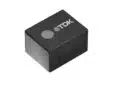
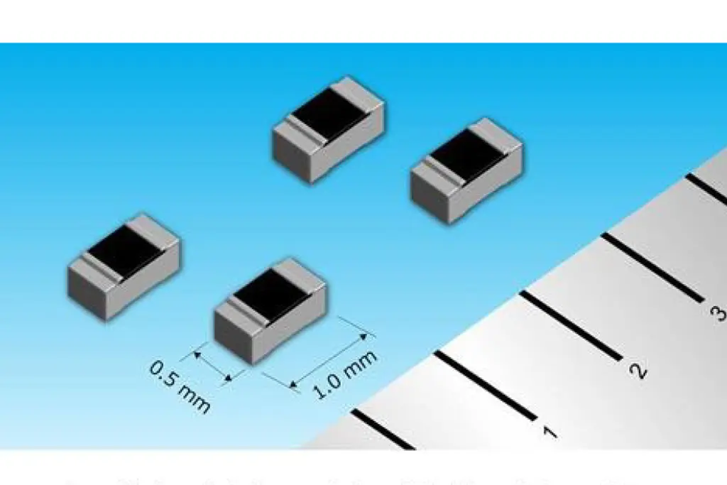
Panasonic Corporation has developed a 0402 size, high precision thin film chip resistor that helps increase accuracy and decrease electro-static discharges risk in automotive ECUs and industrial robots.
Osaka, Japan – Panasonic Corporation has developed a 0402 size, high precision thin film chip resistor that achieves the most robust electro-static discharge (ESD)[1] protection*1 in resistor field. Mass production is planned to start from June 2018. The resistor will help increase accuracy and decrease ESD risk in the power supply units and automotive electronic control units (ECUs), industrial robots, etc.
The need for anti-ESD design in ECUs has been growing with the ever-increasing use of electronics in vehicles. In addition, along with the development of autonomous vehicles as well as environmentally friendly vehicles that feature improved fuel efficiency, ECUs have become increasingly compact and accurate. For this reason, compact, high precision, and high anti-ESD performance resistors are required for such ECUs. The thin film chip resistor, which achieves the industry’s most robust ESD protection while remaining compact and high precision, has been developed based on Panasonic’s proprietary thin film formation technology.
Panasonic’s new chip resistor have the following features:
- Small size, high precision thin film chip resistor, which achieves the industry’s most robust ESD protection*1, for improved anti-electro-static performance and accuracy in control circuits
Anti-ESD performance: HBM[2] 1kV*2, more than 2.5 times better than Panasonic’s conventional products*3
Temperature coefficient of resistivity (T.C.R.): ± 5 × 10⁻⁶/°C,
Resistance tolerance: ± 0.05% - Heat shock performance and long-life-time use capability suitable for automotive applications
Heat shock condition: -55 to 155°C, 1,000 cycles*4, equivalent to Panasonic’s conventional products*3 - Superior anti-sulfur corrosion robustness for improved reliability in control circuits
Hydrogen sulfur life time: 1,000 h*5
Notes:
*1: As a 0402-size, high precision (temperature coefficient of resistivity: ±5 × 10⁻⁶/°C or less, resistance tolerance: ± 0.05% or less) thin film chip resistors, as of March 22, 2018 (Panasonic data)
*2: In 0402-size, thin film chip resistors compliant with standard AEC-Q200 Class 1C
*3: Panasonic’s conventional products (ERA2A series of 0402-size, thin film chip resistors)
*4: Actual values in the company’s standard test conditions (temperature conditions: -55°C for 30 min, 155°C for 30 min)
*5: Actual values in the company’s testing standards (H2S concentration: 3 ppm, temperature: 40°C, relative humidity: 90 to 95% RH)
Suitable Applications:
Automotive:
Control and power circuits in engine ECUs, hybrid electric vehicle (HEV) and EV inverters, anti-lock brake systems, and telematics communication units (TCUs)
Industrial:
Control circuits in industrial robots, precision machine tools, FA control equipment, measuring instruments, and servers
Product Features:
1. Small size, high precision thin film chip resistor, which achieves the industry’s most robust ESD protection, for improved electro-static performance and accuracy in control circuits
Small size and high precision chip resistors are required for the miniaturization of ECUs as well as to achieve increased sensor accuracy needed in autonomous driving technologies. In addition, together with the increasing use of electronics in vehicles, sudden ESDs can cause malfunctions and breakdowns of equipment. ESD measures are therefore required. The structure of the resistive film in conventional compact thin film chip resistors is prone to instantaneous over-voltage occurrences such as ESDs, resulting in local high-loads. This, in turn, causes the resistors to break down more easily. The compact, high precision thin film chip resistor, which achieves the industry’s highest ESD performance, was developed based on Panasonic’s proprietary thin film formation technology in order to decrease local voltage loads due to over-voltage. In addition to providing highly accurate control of input and output signals in amplifier and control circuits, the company’s new thin film chip resistor makes it possible to do away with some of the equipment and restrictions on handling that were necessary as part of the mounting process of thin film resistors in order to reduce ESDs.
2. Heat shock performance and long-life time make the new chip resistor capable and suitable for automotive applications
In environments with wide temperature range, thermal stress due to the difference in the coefficient of linear expansion between the chip resistor and the mounting board is repeatedly applied, causing cracks in the solder fillets[3], eventually resulting in a variation in resistance. Long-term use was therefore an issue. By making use of Panasonic’s proprietary electrode structure which incorporates a buffer layer inside the electrode, this new product suppresses crack propagation occurring in the solder fillets to achieve thermal shock resistance appropriate for automotive applications. It is suitable for equipment such as integrated electromechanical modules which require to be operated in environments that are subject to extreme temperature fluctuations or over long periods of time.
3. Superior sulfidation resistance for improved reliability in control circuits
Sulfur compounds are present in various forms in the atmosphere: automobile exhaust gas, hot spring sulfur gas, etc. Exposing a chip resistor to sulfur compounds causes sulfidation of the electrodes, which may result in a variation of the resistance value. In recent years, demand for sulfidation-resistant resistors has been increasing in order to improve the long-term reliability and safety of various automotive and industrial equipment control circuits. By selecting electrode materials highly resistant to sulfidation and making use of its proprietary methods, Panasonic has developed a resistor that offers superior sulfidation resistance for improved reliability in control circuits. The resistor is also suitable for use in industrial robots that require sulfidation resistance.
Basic Specifications:
| Series name | ERA2V Series | ERA3V Series | ERA6V Series |
|---|---|---|---|
| Chip size (mm) Chip size (inch) |
1005 0402 |
1608 0603 |
2012 0805 |
| Rated power [W] | 0.063 | 0.1 | 0.125 |
| Limiting element voltage [V] | 25 | 75 | 100 |
| Resistance range [Ω] | 47 to 100k | 47 to 330k | 47 to 1M |
| Resistance tolerance [%] | ± 0.05, ± 0.1 | ||
| Temperature coefficient of resistance (T.C.R.) [× 10-6/°C] |
± 5, ± 10, ± 15, ± 25 | ||
| Category temperature range [°C] | -55 to 155 | ||
* Thin film chip resistor sizes available: 0402, 0603, and 0805.
* The resistance tolerance and temperature coefficient of resistance (T.C.R.) vary depending on the resistance range.
Term Definitions:
- [1] Electro-Static Discharge (ESD)
- Phenomenon in which the accumulated charge (static electricity) resulting from the friction and separation of materials is discharged at once upon contact with a conductive material. Such discharges may damage electronic components and circuits.
- [2] Human Body Model (HBM)
- The ESD models include the Charged Device Model (CDM), the Machine Model (MM), and the Human Body Model (HBM). The HBM is the most popular model for evaluating electronic components. It is used as a model for discharges from the human body or charged materials to electronic components.
- [3] Solder Fillet
- When mounting electronic components, the electrodes of the electronic components are soldered onto the copper pattern of a printed circuit board using heat-melted solder. Once an electronic component has been soldered, the triangular solder portion joining the electrode of the electronic component to the copper pattern of the printed circuit board is called “solder fillet.”