


This paper elaborates on problematic of ceramic capacitors MLCC capacitors cracks – literature survey and practical experiments to develop methodology to induce electrode-to-electrode cracks without deterioration of the capacitor’s immediate electrical parameters. In the next step these capacitors are subjected to thermal vacuum and high temperature life test to evaluate its impact to space flight operating conditions.
The paper was presented by Tomas Zednicek, EPCI European Passive Components Institute, Lanskroun, Czech Republic at the 3rd PCNS 7-10th September 2021, Milano, Italy as paper No.2.2.
INDUCING OF MLCC CRACKS
Cracks in MLCC ceramic capacitor are, unfortunately, a well know phenomena that can depend to several factors. It is believed to reduce the reliability of the capacitor leading to catastrophic failure like short circuit.
When cracked capacitors are found in space projects the usual practice is to replace the defective parts and/or to solve the root cause of the problem as for example by modifying the assembly parameters to reduce the thermo-mechanical stress during assembly of the capacitor. However, in many cases, it is not possible to solve the issue and projects have to take risks by flying with potential defectives capacitors.
LITERATURE SURVEY
There are number of publications and works dedicated to MLCC cracks issues and evaluation of methods to reveal it by non-destructive methods. The first step of our assessment focused on available literature study.
CRACKS INDUCING METHODS
The literature survey on MLCC capacitors cracks inducing methods can be summarised as follows:
- High-temperature manufacturing processes and materials with different CTEs that are used in MLCCs result in significant built-in mechanical stresses. Deviations from the optimal conditions and some anomalies in the manufacturing process might form hidden defects and reduce the strength of the parts.
- Additional thermo-mechanical stresses associated with soldering and post-soldering handling of the assemblies can increase stresses to the level sufficient for cracking. These cracks might not affect performance of the system initially but result in failures with time of operation.
Teverovsky in its NASA paper proposed to assess the effect of cracking by pressing the surface with a Vickers indenter. Results showed that cracking does not affect capacitance, which is consistent with the results of flex testing when in many cases capacitance recovers when the stress is removed. The parts electrically passed this test, just dissipation factor showed some sensitivity and increases after cracking by 10 to 50%, but remains within the specified limits.
METHODS TO REVEAL MLCC CAPACITOR CRACKS
Commonly used non-destructive techniques to detect cracks include:
- external visual optical examination under magnifying glass / optical microscope
- electrical characterisation
- ultrasonic inspection / SAM
- Xray 2D/3D and tomography / CT scan
Despite substantial efforts that have been made to develop methods for revealing cracks in MLCCs after soldering, none is universal and can detect defective parts reliably. Suitability of crack detection by methods also depends to the size of MLCC capacitors. More methods are suitable for larger MLCC capacitors above 1812 size, only few can be used for 1210 case sizes and smaller.
EXPERIMENTAL
Experimental testing was performed on 1812 case size X7R MLCC readily available part with high CV at this case 22uF 25V parts from leading MLCC manufacturer date code 2030.
THERMO-MECHANICAL SHOCK TEST
The first experiment aims to maximize the thermo shock stress. The test sequence consists of visual inspection pre and post test, basic electrical parameters characterization including third harmonic measurement THD and the thermal shock cycle. The thermal shock followed three cycles of dip into hot 245C solder followed by immersion into a liquid nitrogen -195C. Dwell time between the dips were less than 3s.
Results
- Sample Size: 10 units 1812 MLCC 22uF 25V X7R
- Optical visual inspection under microscope: no microcracks observed under optical microscope
- Electrical Parameters: All pre and post Capacitance, DF and IR parameters were within specification without significant degradation.
- THD Third Harmonic Measurement: without significant degradation.
The test sequence performed on ten samples did not show any signs of surface cracks observable under optical microscope. There was also no deterioration of electrical parameters neither THD voltage after the test.
CRACKS INDUCED BY MECHANICAL PIN STRESS
The second method tried to simulate extreme flex cracks by replicating of Teverovsky’s method with defined mechanical pin stress force to the center of capacitor body.
Test Description
Sharp mechanical pin was applied from top side to the center of the MLCC body. The pin strength was set to the maximum device capability force: 510±10 N. The parts were visually inspected under optical microscope and electrically characterized including THD before and after the test.
Results
- Sample Size: new set of 15 units 1812 MLCC 22uF 25V X7R
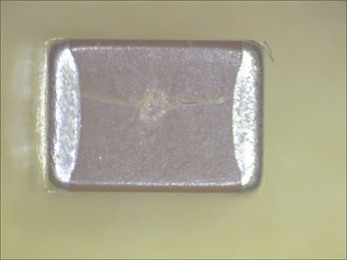
- Optical visual inspection under microscope: Surface cracks with prolonging microcracks visible on the surface of the MLCC body – see Figure 1. Some units crack appeared mildly; others showed remarkable level of mechanical damage.
- Electrical Parameters & THD: Some units resulted in short circuit after the test, others remained within its electrical parameter specification.
Some MLCC samples were considerably mechanically damaged, nevertheless there is not necessary a direct link between the level of mechanical damage and electrical deterioration / short circuit.
Mechanical stress exposure parameters modification
The following mechanical pin stress parameters were modified for detail investigation on its impact to initiation of cracks.
- Pin stress force varied from 350 to 900N (mechanical equipment was also adjusted to be able to apply even higher stress level)
- Pin shape was changed from low radius (sharp) to high radius (blunt)
- THD was continuously measured during the force applied and values at MAX force recorded.
New set of 10 samples were used, samples No. 1-5 were investigated after sharp pin exposure and changing force, the other samples 6-10 with blunt tool pin shape and higher force ratio.
Results
- Low radius sharp pin tool causes a surface damage with microcracks even at lower applied force unlike the blunt tool that even with quite high force 900N did not induced visible surface cracks.
- THD increased during the force being applied in the case of sharp pin tool and returned to original numbers after the force was released – this is in line with Teverovsky results using Vickers hardness measurement tool that referred increase in DF when force is applied and its return afterwards. THD did not increased during the high force applied in the case of blunt pin tool. (that also visually did not damage the MLCC body surface).
REVEALING OF MLCC CRACKS
NON-DESTRUCTIVE ANALYSIS
Non-destructive methods with proof of MLCC crack identification were reviewed with aspects to be suitable for higher sample quantity to pick parts with crack for environmental test.
SAM Scanning Acoustic Microscopy
Scanning Acoustic Microscopy (SAM) has proved to be the most effective tool for the non-destructive detection of very thin (even below 200 nm of thickness) internal anomalies (delamination, voids, cracks, and foreign material) within ceramic capacitors.
Its disadvantage in our test is its limitation for volume testing and associated cost for hundreds of parts.
3D inline X Ray or X-Ray tomography
3D Xray and X-Ray tomography has also a suitable range of resolution to reveal very thin cracks inside of MLCC capacitor body. Nevertheless, the three-dimensional X-ray is time-consuming for a large number of samples and even more expensive than SAM.
2D X Ray
2D X-ray may be suitable for screening of higher volume of samples at affordable cost, thus it was selected to as the non-destructive method to investigate. Downside of the 2D Xray is its limitation to see fine cracks against the projection of the MLCC body.
The 2D Xray images unfortunately could not reveal internal structure of 1812 MLCC capacitors and it may not be suitable for cracks identification.
CROSS-SECTIONING DPA
Cross-sectioning DPA was performed on parts in addition to check effectiveness of the crack-induced methods.
Cracks Induced by Thermo-Mechanical Stress
Ten parts subjected to thermo-mechanical stress test, sectioned and inspected under optical microscope – low and high magnification (x500). Thermal stress induced cross sectioning observations:
- No cracks neither delamination were detected under the optical microscope examination of all ten samples.
- The MLCC test parts showed very high robustness to thermal shock stress – with delta temperature that reach even 440°C. This method may not be suitable to generate cracks in mass scale. ¨
Cracks Induced by Mechanical Pin Stress
Another ten MLCC capacitors of the same PN were subjected to mechanical pin stress exposure and cross-section DPA to study its internal structure.
The repeated test confirmed previous findings that sharp pin force is causing a surface damage with visible microcracks on the MLCC capacitor surface body and third harmonic increases during the force applies. There was no visible surface cracking, neither third harmonic voltage increase during the stress applied in the case of blunt pin type was used. All parts were cross sectioned to see impact of the mechanical pin stress to its internal layers and inner construction. Visual inspection of cross-sectioned parts under optical microscope confirmed delamination and cracks of dielectric layers in almost all cases. (note: the capacitors were electrically measured and confirmed within its specification).
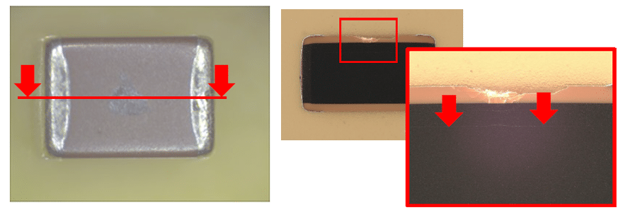
Figure 2. and 3. illustrate view of the typical representative sample No.14 cross section images from low to higher magnification.
Mechanical stress induced cross sectioning observation.
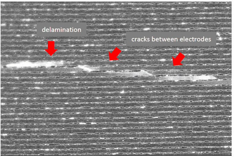
- The cross-sectioning structure analysis confirms presence of major delamination and cracks inside of the MLCC capacitors subjected to mechanical pin force.
- The delamination present alongside the capacitor body in multiple layers with different length from tenth of millimeters to millimeter range (in some cases up to half size of the MLCC active capacitor zone.
- There is no major difference in inner delamination/crack visual or occurrence frequency between sharp or blunt pin types. The major difference is only level of its surface damage.
- The observed cracks can clearly cross whole dielectric layer thickness – from one to the other electrode as shown in Fig.16.
SPACE ENVIRONMENT EVALUATION TESTS
DRY HEAT & THERMAL VACUUM LOAD TEST
Experimental testing was performed on the 1812 case size X7R MLCC relatively high CV, medium voltage parts 22uF 25V parts from leading manufacturer. The parts are readily on stock for purchase from a standard authorized distributor. The test flow diagram used 350 parts of the MLCC 1812 samples split into five groups – see Figure 4.
Test Groups Definition
- Group 1 target acceleration by thermal shock to initiate CTE overstress by high delta thermal shock over 440°C by three cycles of dips into hot +245°C solder followed by immersion into a liquid nitrogen at -195°C.
- Groups 2-4 simulate mechanical overstress such as flex and PCB vibration by mechanical pin force exposure to the MLCC body center. Two pin types are used – low radius, sharp pin that intentionally create microcracks on the surface body, and high radius, blunt pin type that is applying extra force but no surface cracks are allowed.
- Group 2 – low radius sharp pin stress with 300±10 N force, surface microcracks are allowed.
- Group 3 – low radius sharp pin stress with 500±10 N force, surface microcracks are allowed.
- Group 4 – high radius blunt pin stress with 900±10 N force, parts with surface microcracks during optical microscope check to be replaced with new sample.
- Group 5 is a control group without any stress applied.
All parts were visually checked under an optical microscope for presence of micro-cracks and measured electrically before and after the mechanical stress to make sure they are electrically compliant to their specified limit. Measurement of third harmonic distortion THD, in addition was proposed as the most sensitive method to identify any non-linearity defects. Parts that electrically fails specification limits were replaced with new ones so test boards for the tests can be fully occupied.
Dry Heat & Thermal Vacuum Tests
Purpose of the selected tests was to simulate space environmental load to MLCC capacitors with cross electrode cracks by exposure to dry heat and thermal vacuum conditions. All test parts were board mounted prior the tests with visual and electrical parameters check before and after the board mounting. Electrical Characterization was performed according to ESCC 3009 general specification and ESCC 3009/09 detail specification.
Dry Heat Exposure
The test parts were subjected to 125°C dry heat load at 2xVr 2000hrs test measured by 500h steps. The test follow ESCC 3009 general specification and ESCC 3009/09 detail specification.
Thermal Vacuum
The test parts were exposed to thermal vacuum pressure ≤ 50Pa at 85°C, 2000hrs test measured by 500h steps. The first 1k hours power source is set to operate as voltage source at 2xVr constant voltage; the next 1khrs the power source operated as a current source with voltage limitation to 2xVr. Level of constant current was decided based on the first 1k hours data record. Thermal vacuum exposure follow ESCC 2263000 test conditions without polarity change and weight measurement, that was not applicable.
TEST RESULTS
Dry Heat Test Results
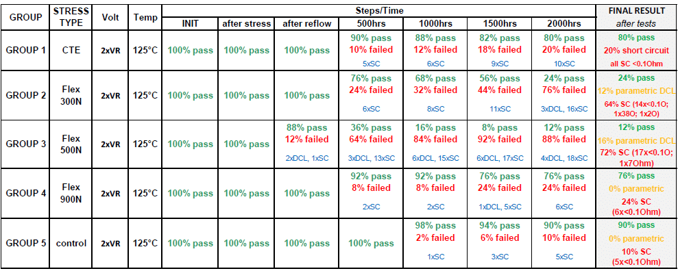
Despite the tested MLCC capacitors show no deviation in electrical parameters after the applied stress, there is a certain percentage of components that begin to fail catastrophically at dry heat test even after 500h in all stressed groups (apart of control group 5).
The test is running at accelerated conditions of 125°C and twice rated voltage. 10% of short circuits were observed after 2000hrs even at control group. CTE stress load test group 1 showed twice higher 20% of short circuits after 2000hours. Short circuits of all test groups were remeasured by Ohmmeter to confirm short circuit failure mode and level of its resistance. Most of the short circuit parts were failing with resistance lower than 0.1 Ohm (lowest resolution of Ohmmeter used), only few were in range of units and tenth of Ohms.
High percentage of Flex stress parts failed short during the test. Group 2 and 3 of parts stressed by sharp pin failed at 80-90% at the end of 2000 hour test, blunt pin stressed parts at 24%.
Thermal Vacuum Test Results
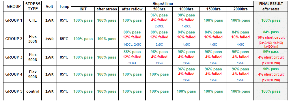
Thermal vacuum test presents a lower stress level compared to the dry heat load as also temperature acceleration factor is lower (85°C vs 125°C). Some DCL parametric and short circuit failures can be seen in the Flex stress sharp pin groups 2 and 3 already after the reflow board mounting with further move of parametric DCL failures into short circuits catastrophic failures during the thermal life test. Overall short circuit failure rate of the flex stress parts was from 4 to 16% after 2000hrs.
Few DCL parametric failures (just slightly above the DCL specification limit) occurred in the CTE stressed group 1 but it did not continue into failures, stabilized instead and there were no failures at final 1500 and 2000hrs measurement. Controlled group did not show any failures during the test.The following charts in figure 11 are showing shift of electrical parameters during the test.
CONCLUSION
SUMMARY AND DISCUSSION
MLCC test capacitors 1812 X7R 22uF 25V were subjected to two type of stress to induce cracks:
1. Thermo-mechanical stress to simulate extreme CTE mismatch load. The load was applied by three cycles of dips into hot solder and liquid nitrogen (dt 440C !).
Results: no microcracks were observed on MLCC body surface, all tested parts electrically passed its specification limits.Cross sectioning of the parts did not find any delamination or cracks inside of the MLCC capacitors inner layers. MLCC capacitors showed high robustness to shock temperature stress. This method may not be suitable to generate cracks inside of the capacitors body.
2. Mechanical stress by sharp pin exposure with defined force to MLCC body surface center to stimulate extreme flex stress.
Results: the mechanical pin causes a local damage to MLCC surface depending to the applied force and radius of the pin. Level of electrical damage was monitored continuously during the applied mechanical force by THD analysis. THD was proofed as the most sensitive method to detect electrical behaviour changes.
Changes in electrical parameters were noted only in the case of use of sharp, low radius pins with visible surface layer damage. In case of blunt pin force applied no impact THD was measured, even at very high force 900N. Some MLCC samples were considerably mechanically damaged by sharp pin, nevertheless there is not necessary a direct link between the level of mechanical damage and electrical deterioration / short circuit.
Cross sectioning of the MLCC capacitors after the pin force mechanical stress confirm presence of delamination and cracks inside the capacitor body. Delamination can present in more layers between the electrode and dielectric length from tenth of millimeter-to-millimeter scale. The cracks may present across the whole dielectric thickness bridging opposite electrodes.
The test sequence aim to induce cracks by two different methods – CTE and mechanical overstress – and expose the test parts mounted on a PCB to space dry heat & thermal vacuum life tests.
Test Results
The MLCC 1812 X7R 22uF 25V capacitors with induced cracks / internal damage exhibited quite high range of failures during exposure to accelerated dry heat and thermal vacuum tests.
The dry heat test running at higher temperature 125°C is showing higher degradation rate of the stressed parts vs the thermal vacuum test. This may be driven by higher test temperature suggesting the temperature acceleration may be one of the key parameters initiating failures. The parts without visible damage stressed by extreme CTE load (group 1) and Flex stress by blunt tool (group 4) did not show any deterioration of electrical parameters after board mounting but begin to electrically fail for high DCL and catastrophic short circuit (R<0.1Ohm) even at initial 500hours of exposure to the dry heat load. Control sample without any stress show some 2% failures at 1000hrs and 10% failures at 2000hrs, nevertheless CTE exposed parts had twice higher percentage of failures at this time.
DCL and SC failures were also observed during thermal vacuum test but only in the case of groups 2 and 3 flex stressed parts by sharp pin with significant mechanical surface damage. Parts without visible damage pass the initial test steps and 2000hours without any electrical failures / minor parametric issues.
DCL histogram do not show any continuous DCL degradation during the test, also there are not many fliers from the main distribution. The typical short circuit with low ohmic failure is of sudden degradation nature – no graduate DCL deterioration within 500h steps is noticed. The SC parts fail from the main DCL distribution at previous measurement step. It is thus impossible to identify such failures by statistical dynamic screening etc. at earlier stage.
ACKNOWLEDGEMENT
The work described in this report was supported by ESA under contract No. 4000131515/20/NL/KML/ig “Reliability Assessment of Cracks in Ceramic Capacitor in Space Condition (Life test under Vacuum) – Impact on Standards”.
REFERENCES
- Teverovsky.A.; „Cracking Problems in Low-Voltage Chip Ceramic Capacitors“, NASA NEPP ASRC Federal Space and Defense, 2018. https://nepp.nasa.gov/files/29931/NEPP-BOK-2018-Teverovsky-Paper-NEPPWeb-BOK-Cracking-MLCC-TN65668.pdf