Passive Components Blog
No Result
View All Result
  • Home
  • NewsFilter
    • All
    • Aerospace & Defence
    • Antenna
    • Applications
    • Automotive
    • Capacitors
    • Circuit Protection Devices
    • electro-mechanical news
    • Filters
    • Fuses
    • Inductors
    • Industrial
    • Integrated Passives
    • inter-connect news
    • Market & Supply Chain
    • Market Insights
    • Medical
    • Modelling and Simulation
    • New Materials & Supply
    • New Technologies
    • Non-linear Passives
    • Oscillators
    • Passive Sensors News
    • Resistors
    • RF & Microwave
    • Telecommunication
    • Weekly Digest

    Samsung Electro-Mechanics Releases High-Capacitance MLCCs for AI Server Applications

    Samsung Electro-Mechanics Releases 165C Automotive 0806 Size Power Inductors

    Coupled Inductors Circuit Model and Examples of its Applications

    Würth Elektronik Introduces LTspice Models for ESD Products

    Capacitor Ripple Current Testing: A Design Consideration

    TDK Releases 0201 High-Frequency Smallest Inductors

    Coilcraft Extends Air Core RF Inductors

    Bourns Releases Automotive 1W Flyback Transformer

    Wk 20 Electronics Supply Chain Digest

    Trending Tags

    • Ripple Current
    • RF
    • Leakage Current
    • Tantalum vs Ceramic
    • Snubber
    • Low ESR
    • Feedthrough
    • Derating
    • Dielectric Constant
    • New Products
    • Market Reports
  • VideoFilter
    • All
    • Antenna videos
    • Capacitor videos
    • Circuit Protection Video
    • Filter videos
    • Fuse videos
    • Inductor videos
    • Inter-Connect Video
    • Non-linear passives videos
    • Oscillator videos
    • Passive sensors videos
    • Resistor videos

    Coupled Inductors Circuit Model and Examples of its Applications

    Inductor Resonances and its Impact to EMI

    Highly Reliable Flex Rigid PCBs, Würth Elektronik Webinar

    Causes of Oscillations in Flyback Converters

    How to design a 60W Flyback Transformer

    Modeling and Simulation of Leakage Inductance

    Power Inductor Considerations for AI High Power Computing – Vishay Video

    Coupled Inductors in Multiphase Boost Converters

    VPG Demonstrates Precision Resistor in Cryogenic Conditions

    Trending Tags

    • Capacitors explained
    • Inductors explained
    • Resistors explained
    • Filters explained
    • Application Video Guidelines
    • EMC
    • New Products
    • Ripple Current
    • Simulation
    • Tantalum vs Ceramic
  • Knowledge Blog
  • Suppliers
    • Who is Who
  • Events
No Result
View All Result
Passive Components Blog
No Result
View All Result

ROHM expands its PSR series with ultra-low ohmic shunt resistors for automotive and industrial applications

26.1.2018
Reading Time: 3 mins read
A A

source: Rohm news

Compact designs contribute to improved performance in high power applications. With its PSR100 series, ROHM offers a significantly more compact version of its proven PSR series. The PSR100 series ultra-low ohmic shunt resistors have a high-power capability and are suited to current measurement in automotive and industrial applications.

RelatedPosts

Samsung Electro-Mechanics Releases High-Capacitance MLCCs for AI Server Applications

Samsung Electro-Mechanics Releases 165C Automotive 0806 Size Power Inductors

Coupled Inductors Circuit Model and Examples of its Applications

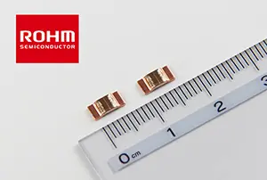
The new shunt resistors, which are based on a high-performance metal alloy as the resistive element, feature superior temperature coefficients (TCR) from 50ppm to 150ppm. Thanks to ROHM’s innovative precision welding technology, they deliver a high rated power of 3W coupled with an ultra-compact form factor of 6.35mm x 3.05mm. Their resistance range covers 0.3mΩ to 3.0mΩ. The resistance tolerance is specified with F (1%). The operating temperature range is –55°C to +170°C.

The PSR100 series is the ideal solution for automotive and industrial applications as well as many other areas with high requirements in terms of performance and size. These include for example on-board chargers, electronic compressors and EPS in motor vehicles in addition to UPS and base stations.

PSR Series Shunt Resistors

High power applications supported
Shunt resistors are widely used in the automotive and industrial sectors for measuring current in high power applications. Due to the increasing demand for electric vehicles and the need to provide greater safety and efficiency, the automotive sector is seeing a shift towards computerisation and electro-mechanical systems. This has led to an increasing number of small motors and ECUs being used in the vehicles, which in turn drives up the demand for compact shunt resistors that can support higher power. To cater to this demand, ROHM has expanded its PSR series of high power low-resistance shunt resistors.

Higher rated power achieved using precision welding technology and high performance alloy

Excellent temperature coefficient of resistance – even in the ultra-low resistance region
Generally, the lower the resistance, the higher the temperature coefficient of resistance (TCR). In line with this, ROHM used a high-performance alloy as a high-resistivity metal, which ensures superior TCR, even in the ultra-low resistance region. The latest version is currently available with resistances from as low as 0.3mΩ, thus facilitating a wider range of applications.

Superior temperature coefficient of resistance - even in the ultra-low-ohmic region

Circuit Diagram

Circuit Diagram

Specifications

Part No. Size (mm)
[inch]
Rated Power
(+70ºC)
Resistance
Tolerance
Temperature*
Coefficient
of Resistance (ppm/ºC)
Resistance
Range (mΩ)
Operating Temp.
Range (Cº)
NEWPSR100 6.35 x 3.05
[2512]
3W F(±1%) ±150 0.3 -55ºC to + 170ºC
±115 0.5
±100 1.0
±50 2.0, 3.0
PSR400 10 x 5.2
[3921]
4W F(±1%) ±225 0.2◊
±175 0.3, 0.5
±75 1.0, 2.0, 3.0
PSR500 15 x 7.75
[5931]
5W F(±1%) ±250 0.1◊
±225 0.2
±150 0.3, 0.4, 0.5
±75 1.0, 2.0

◊ These products are under development, and therefore the specifications are subject to change without notice. Please contact a ROHM sales representative for more information.
* +20ºC to +125ºC

Terminology

TCR (Temperature Coefficient of Resistance)
The lower the value, the less resistance change with a change in ambient temperature. This makes it possible to suppress variations during device operation.

Related

Recent Posts

Samsung Electro-Mechanics Releases 165C Automotive 0806 Size Power Inductors

21.5.2025
13

Capacitor Ripple Current Testing: A Design Consideration

21.5.2025
34

Coilcraft Extends Air Core RF Inductors

20.5.2025
11

Bourns Releases Automotive 1W Flyback Transformer

19.5.2025
14

Highly Reliable Flex Rigid PCBs, Würth Elektronik Webinar

15.5.2025
27

Würth Elektronik Releases High Performance TLVR Coupled Inductors

15.5.2025
34

YAGEO Extends Rectangular Aluminum Electrolytic Capacitor Family

15.5.2025
53

Littelfuse Releases Industry-First SMD Fuse with 1500A Interrupting Rating at 277V

14.5.2025
13

TDK Unveils Industry Highest Rated Current Multilayer Chip Beads

14.5.2025
19

Vishay Releases Automotive SMD Thick Film Power Resistor for Enhanced Protection Against Short Transient Pulses

14.5.2025
11

Upcoming Events

May 28
16:00 - 17:00 CEST

Power Over Data Line

View Calendar

Popular Posts

  • Buck Converter Design and Calculation

    0 shares
    Share 0 Tweet 0
  • Boost Converter Design and Calculation

    0 shares
    Share 0 Tweet 0
  • Flyback Converter Design and Calculation

    0 shares
    Share 0 Tweet 0
  • How to Design an Inductor

    0 shares
    Share 0 Tweet 0
  • LLC Resonant Converter Design and Calculation

    0 shares
    Share 0 Tweet 0
  • Capacitor Ripple Current Testing: A Design Consideration

    0 shares
    Share 0 Tweet 0
  • Ripple Current and its Effects on the Performance of Capacitors

    3 shares
    Share 3 Tweet 0
  • Dual Active Bridge (DAB) Topology Explained

    0 shares
    Share 0 Tweet 0
  • Flying Capacitors Explained

    0 shares
    Share 0 Tweet 0
  • What is a Dielectric Constant and DF of Plastic Materials?

    4 shares
    Share 4 Tweet 0

Newsletter Subscription


Passive Components Blog

© EPCI - Leading Passive Components Educational and Information Site

  • Home
  • Privacy Policy
  • EPCI Membership & Advertisement
  • About

No Result
View All Result
  • Home
  • Knowledge Blog
  • Premium Suppliers

© EPCI - Leading Passive Components Educational and Information Site

This website uses cookies. By continuing to use this website you are giving consent to cookies being used. Visit our Privacy and Cookie Policy.
Go to mobile version