Passive Components Blog
No Result
View All Result
  • Home
  • NewsFilter
    • All
    • Aerospace & Defence
    • Antenna
    • Applications
    • Automotive
    • Capacitors
    • Circuit Protection Devices
    • electro-mechanical news
    • Filters
    • Fuses
    • Inductors
    • Industrial
    • Integrated Passives
    • inter-connect news
    • Market & Supply Chain
    • Market Insights
    • Medical
    • Modelling and Simulation
    • New Materials & Supply
    • New Technologies
    • Non-linear Passives
    • Oscillators
    • Passive Sensors News
    • Resistors
    • RF & Microwave
    • Telecommunication
    • Weekly Digest

    Bourns Increases Maximum Inductance Values of Semi-Shielded Power Inductors

    YAGEO Unveils Next Gen BMS Isolation Transformers

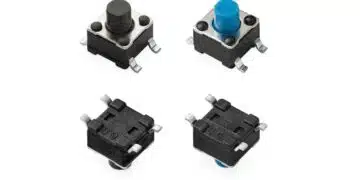
    Littelfuse Compact Tactile Switch Offers Low-Noise Switching and Dust Protection

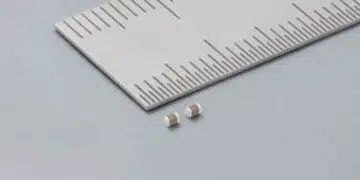
    Murata Announces Mass Manufacturing of World’s First 0402 47µF MLCC

    Bourns Releases SMD Chip High-Power Metal Strip Current Sense Resistors in 2010 Case

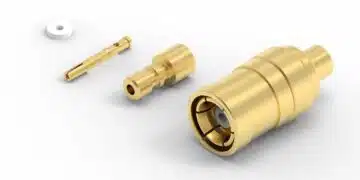
    Würth Elektronik Releases High-Frequency Connectors for Antenna Cables

    Murata Releases First High-Frequency XBAR Filter for Next-Gen Networks

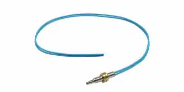
    Vishay NTC Immersion Thermistor Delivers Fast Response in Liquid Cooled Automotive Systems

    Wk 27 Electronics Supply Chain Digest

    Trending Tags

    • Ripple Current
    • RF
    • Leakage Current
    • Tantalum vs Ceramic
    • Snubber
    • Low ESR
    • Feedthrough
    • Derating
    • Dielectric Constant
    • New Products
    • Market Reports
  • VideoFilter
    • All
    • Antenna videos
    • Capacitor videos
    • Circuit Protection Video
    • Filter videos
    • Fuse videos
    • Inductor videos
    • Inter-Connect Video
    • Non-linear passives videos
    • Oscillator videos
    • Passive sensors videos
    • Resistor videos

    Accelerating Full Bridge LLC Resonant Converter Design with Frenetic AI

    Understanding Switched Capacitor Converters

    Coupled Inductors Circuit Model and Examples of its Applications

    Inductor Resonances and its Impact to EMI

    Highly Reliable Flex Rigid PCBs, Würth Elektronik Webinar

    Causes of Oscillations in Flyback Converters

    How to design a 60W Flyback Transformer

    Modeling and Simulation of Leakage Inductance

    Power Inductor Considerations for AI High Power Computing – Vishay Video

    Trending Tags

    • Capacitors explained
    • Inductors explained
    • Resistors explained
    • Filters explained
    • Application Video Guidelines
    • EMC
    • New Products
    • Ripple Current
    • Simulation
    • Tantalum vs Ceramic
  • Knowledge Blog
  • Suppliers
    • Who is Who
  • Events
No Result
View All Result
Passive Components Blog
No Result
View All Result

TDK EPCOS Robust Power AC Filter Film Capacitors Design Explained

8.6.2020
Reading Time: 6 mins read
A A

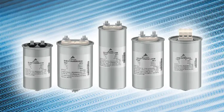
In the input/output circuits of power electronics, filtering is required to achieve the necessary power quality and EMC performance. With this in mind, TDK has developed new series of EPCOS AC filter capacitors, which excel thanks to their high degree of reliability and long service life.

AC filter capacitors are supplied with very high power ratings. According to the IEC-61071 standard for capacitors in power electronics, a safety device is mandatory for power capacitors, which activates the capacitors in the event of a fault. Previously, internal connection wires of the winding tended to be used as the safety device, which featured a defined notch, also known as the breakaway quick-closing device. In the event of a short circuit or extreme overload of the capacitor, the pressure inside of capacitor increases, the groove expands, and the connection wire tears at the notched point. Figure 1 illustrates the principle.

RelatedPosts

Bourns Increases Maximum Inductance Values of Semi-Shielded Power Inductors

YAGEO Unveils Next Gen BMS Isolation Transformers

Littelfuse Compact Tactile Switch Offers Low-Noise Switching and Dust Protection

The connection wire is soldered to the screw terminal connection. This is however associated with several disadvantages, as the soldering process can result in discoloration of connections (oxidation) and peeling of paint. Furthermore, in adverse conditions, liquid resin which leaks out of the capacitor can damage other electronic components. This design has also the disadvantage that it is sensitive to vibrations. In the event of a more severe mechanical impact, the phase connection wire can be disconnected (figure 1) damaging the capacitor completely. That happens mainly in applications such as in machines with strong vibrations, such as compressors and wind generators or during transport, whereby the respective phase is interrupted stopping the flow of electrical current leaving capacitor out of operation.

[---Image_alt---] Figure1_en
Figure 1: In the event of an overload the groove expands and the notched point of the connection wire tears
[---Image_alt---] Figure2_en
Figure 2: Thanks to the safety device design, the soldering process of connection wires is now a thing of the past. Furthermore, this results in improved reliability.

Increased safety thanks to solderless connection

TDK has now developed a new, more reliable safety device, which is to be used by AC filter capacitors of the new EPCOS MKD-AC series B3237* (upgrade of old series EPCOS MKP-AC B3236*). Solid screw connections are used here, through which the soldered connection wire is no longer routed. During normal operation, the screw connections press on their bottom side on the copper strips, which contact the capacitor windings. If the capacitor is now damaged, the cover is lifted with the screw connections (homogenous horizontal force) and the contact to the copper strips is interrupted, which ultimately activates the safety device of the capacitor. In addition to preceding soldering techniques with all its disadvantages, this design results in considerably increased mechanical robustness against vibration. Figure 2 illustrates the principle.

Increased service life thanks to enhanced thermal design

Another critical point is the service life of capacitors with the standard safety device design. The lifetime estimations show the standard expected lifetime of 100,000 hours  at +85 °C hotspot  based on endurance test results performed according to IEC61071 standard. The service life of the metalized film essentially depends on the rated voltage and hotspot temperature (Ths) during operation, as it is shown in figure 3. 

[---Image_alt---] Figure3_en
Figure 3: Expected lifetime in hours at different hotspot temperatures (Ths) and voltages VRMS

In the conventional design, the connection wire is in the center of the capacitor winding. In the old MKP-AC design during operation, a current flows through the copper connection cable with a specific effective value, which increases the temperature of the wire. Consequently, the temperature of the winding increases in the old design, whereby the temperature difference between the middle and outside could go up to 15 to 20° Celsius degrees. This consequently lead to a decrease in service life.

TDK Electronics has therefore significantly improved the design of its Filter capacitor upgrading the old series MKP-AC B3236 to the new series MKD-AC B3237*. Instead of round wires, flat copper cables with a lower resistance are used, which reduces heat generation. Furthermore, these flat cables are fitted outside the winding and therefore offer good thermal coupling to the aluminum can of the capacitor, which results in better heat dissipation. As such, the newly designed capacitors have a service life of at least 100,000 hours during operation with rated voltage at maximum hotspot temperature. Figure 5 illustrates the design principle.

[---Image_alt---] Figure4_en
Figure 4: AC filtering power capacitor with notch-wire safety device
[---Image_alt---] Figure5_en
Figure 5: By using copper strips with low resistance, which have good thermal coupling to the capacitor can, heat dissipation is improved which increases the service life of the capacitor.

Space-saving due to 3-phase design

Powerful converters for drives or photovoltaic and wind energy power plants are built in a 3-phase design in today’s industry. Many manufacturers of power electronics continue to use three single capacitors for input/output filtering.. 3-phase filter capacitors do however offer a number of advantages:  

  • Less space required
  • Reduced volume
  • Lower weight
  • Fewer components
  • Reduced risk of failure
  • Less manpower

One specific example is: One 3-phase EPCOS MKD-AC capacitor B32377A3107J030 can replace three units of single phase capacitors (B32373A3107J030) for a three-phase electrical load and in doing so, achieves the same electric strength and capacitance needed. 

For this particular case, the solution with 1 piece of a 3-phase capacitor has a 22% percent less volume (without considering space between the capacitors) and a 50% percent less weight in comparison to the 3 pieces needed of 1-phase capacitor solution. Furthermore, the 3-phase solution is up to 40% percent cheaper, based on the acquisition costs of the capacitors alone. Also, fewer cable connections are required (3 phase cables for 3-phase capacitor instead of 6 phase cables for 3 pieces of 1-phase capacitor), less workforce (capacitor mounting), and the risk of failure is lower. 

[---Image_alt---] Figure6_en
Figure 6: The 3-phase solution provides considerable advantages in terms of space requirements, weight and reliability when compared to using three individual 1-phase capacitor solution.

The benefits of one 3-phase filter capacitor compared to three units of single-phase capacitor solution at a glance:

Parameter1 Ph3 Ph
Capacitance [µF]100100
Voltage [Veff]330330
Current [Ieff]3633
Weight [kg]0,71,4
Radius [mm]7575
Height [mm]117275
Total solution3 x 1Ph1 x 3 Ph
Number of phase cables [-]63
Total weight [kg]2.11.4
Total volume [cm³]62034860
Total capacitance [µF]3×1003×100

Authors: Nicolás Faúndes and Dennis Huang, both TDK Electronics

Related

Source: TDK EPCOS

Recent Posts

Bourns Increases Maximum Inductance Values of Semi-Shielded Power Inductors

11.7.2025
1

YAGEO Unveils Next Gen BMS Isolation Transformers

10.7.2025
10

Littelfuse Compact Tactile Switch Offers Low-Noise Switching and Dust Protection

10.7.2025
6

Murata Announces Mass Manufacturing of World’s First 0402 47µF MLCC

10.7.2025
15

Bourns Releases SMD Chip High-Power Metal Strip Current Sense Resistors in 2010 Case

10.7.2025
7

VINATech Supercapacitors Enhance Automotive Safety with Reliable E-Latch Emergency Power

7.7.2025
37

Exxelia Unveils Advanced Components for the Medical Device Industry

9.7.2025
47

TDK Introduces High Current 80VDC Board-Mount EMI Filters

2.7.2025
29

Bourns Releases High Heat Tolerant TO-227 Thick Film Resistor

2.7.2025
19

TDK Increases Current Ratings of Automotive Thin-Film Power Inductors

1.7.2025
25

Upcoming Events

Jul 16
16:00 - 17:00 CEST

Design a 2kW PSFB converter before your cold drink gets warm

Jul 23
13:00 - 14:00 CEST

PCB design for a Smartwatch

Jul 29
16:00 - 17:00 CEST

Impact of Elevated Voltage and Temperature on Molded Power Inductors in DC/DC converters

View Calendar

Popular Posts

  • Buck Converter Design and Calculation

    0 shares
    Share 0 Tweet 0
  • Boost Converter Design and Calculation

    0 shares
    Share 0 Tweet 0
  • Flyback Converter Design and Calculation

    0 shares
    Share 0 Tweet 0
  • What is a Dielectric Constant and DF of Plastic Materials?

    4 shares
    Share 4 Tweet 0
  • LLC Resonant Converter Design and Calculation

    0 shares
    Share 0 Tweet 0
  • Ripple Current and its Effects on the Performance of Capacitors

    3 shares
    Share 3 Tweet 0
  • How to Design an Inductor

    0 shares
    Share 0 Tweet 0
  • Dual Active Bridge (DAB) Topology Explained

    0 shares
    Share 0 Tweet 0
  • Why Low ESR Matters in Capacitor Design

    0 shares
    Share 0 Tweet 0
  • SEPIC Converter Design and Calculation

    0 shares
    Share 0 Tweet 0

Newsletter Subscription


Passive Components Blog

© EPCI - Leading Passive Components Educational and Information Site

  • Home
  • Privacy Policy
  • EPCI Membership & Advertisement
  • About

No Result
View All Result
  • Home
  • Knowledge Blog
  • Premium Suppliers

© EPCI - Leading Passive Components Educational and Information Site

This website uses cookies. By continuing to use this website you are giving consent to cookies being used. Visit our Privacy and Cookie Policy.
Go to mobile version