


The sense of touch is a critical element into an immersive user experience. Haptics is, essentially, the science of touch. According to IDTechEx, the haptics market will be worth nearly $5bn by 2025. How can an electronic device enhance the user experience through interacting with the sense of touch? Haptic technologies have been present in gaming and cell phone for a long time. More recent developments are enabling far more sophisticated user experiences.
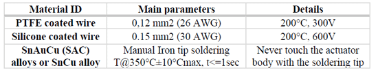
KEMET Electro-Mechanical Polymer-based actuators are thin, light, flexible, and provide a wide range of haptic feedback that are mild, pleasing and distinguishable from one another thereby providing a wide range of localized feedback.
The paper was presented by Marina Innocenti, KEMET Electronics, Bologna, Italy at the 3rd PCNS 7-10th September 2021, Milano, Italy as paper No.4.2.
HAPTIC SENSORS INTRODUCTION
INTRODUCTION
The term “haptic” comes from a greek word haptikos, which means connect to sense of touch, and greek verb “haptesthai” which means to contact or to touch. Specifically, it describes the possibility to sense and manipulate the surrounding physical or virtual environment through touch [1]. The touching process can be performed by humans, machines, or a combination of both and the final feedback given to the user can be enhanced including additional sensory modalities like vision or hearing. The application of haptics technologies has encouraged various disciplines such as mechanics, biomedical, psychology, neurology, engineering and computer science to deeply investigate the relation between human touch and force feedback. [2].
Haptic technologies make use of actuators to apply forces to surfaces (skin in case of direct human contact) to create a tactile feedback. The actuators are able to generate, starting from an electrical stimulus, a mechanical motion. The first generation of haptic actuators made use of electromagnetic technology such as vibratory motors which displayed only a limited number of feedback sensations. Starting from these technologies, research led to various solution such as devices with touch coordinate specific responses or products with fully customizable actuation. The last generation of actuators is incorporating the most advanced haptic technology concepts, enabling pressure sensitivity and proportional response to the amount of force applied [3].
The efficiency, performance, and advancement of haptic interfaces depend on the type of feedback, manoeuvrability, manipulability, stimulation amplitude and actuator technology of the final product [4]. Factors such as feedback speed and force or interaction mode should also be considered in the design phase for effective results [5]. Considering only the feedback type, various example such as force, vibrotactile, and electrotactile feedback systems can be found, with a majority of the haptic devices based on force and vibrotactile feedback [2,6]. With many kinds of information to be defined for each end-use application and the necessity to respond quickly to market, the importance of haptic devices has skyrocketed [7].
Specifically, three different areas of haptic technologies have been defined until now: human haptics, machine haptics, and computer haptics [8]. Human haptics are based on kinesthetic information and tactile information. Machine haptics is defined as the use of machines to replace human touch autonomously or through haptic interfaces. Computer haptics has become prominent over the years and it is related to creating and rendering a tactile feedback feel of virtual objects to the user with the help of algorithms and software [3].
Even if produced by different technologies, the final haptic feedback perception of the final user belongs to one of the most complex human sensory systems which comprises the skin, our largest sensory organ, by involving signal exchange between the musculoskeletal system, the peripheral sensory nervous system of touch and the brain [9-10]. It subdivides in two main categories encompassing the kinesthetic (movements, forces and their sensory information) and tactile feedback. The tactile sensitivity to pressure, vibration and texture is the outcome of sensory neural endings and specialized receptors that are responsible for capturing mainly mechanical and thermal signals, thus providing enormous amount of information regarding our interaction with the environment as well as the state of human body.
The most sensitive areas of human skin are located at the pads of our fingertips, comprising thousands of sensory nerves per centimeter square of skin [11]. Human skin is composed by three primary layers [12] (the epidermis, the dermis and the subcutaneous) and it is divided into two main types (hairy and glabrous), each one presenting different characteristics regarding biomechanics, anatomy and sensory resources. The most part of human body is covered by hairy skin, while the glabrous skin, which has hairless and thicker characteristics, is present on the parts of the body such as hands, fingers and the soles of the feet, that are mostly used to interact with our surroundings by means of touch [13] –reasonably being these the main areas of focus for the development of haptic interfaces.
The successful re-creation of tactile haptic feedback should exploit the presence of mechanoreceptors located in the skin by mimicking the external stimulus within the appropriate spectrotemporal sensitivity and dynamic range characteristics referent to each type of the receptors present in the skin area of interest. In this manner, it would be possible to induce a natural response of the mechanoreceptors that will transduce the deformation of the skin into neural information (electrical action potentials or spikes) which are carried into the brain by the nerve fibers through the medial lemniscal pathway creating a conscious tactile perception [14], [15].
As starting point, it is vital to understand the function and the response characteristics of mechanoreceptors present in the glabrous skin. Four types of low-threshold mechanoreceptors are present in glabrous skin, each one responding in a different manner regarding skin deformation. Merkel cells and Meissner corpuscles are located under the epidermis, while Pacinian corpuscles and Ruffini endings are positioned in a deeper tissue. Merkel cells have round shape and are the most numerous receptors, reaching densities over 500 cm-2 in some areas of glabrous skin, such as fingertips, with single cell dimension of approximately 10 μm in diameter [16].
They are slowly adapting to external stimuli with receptive field size of approximately 0.5 mm, displaying large interval of frequency response, from low frequency skin vibration (few Hz) and up to frequencies over 100 Hz. These types of mechanoreceptor display good response towards static skin deformation as well as to transient skin deformation [17], [18]. The second in highest density mechanoreceptors are the oval shaped Meissner corpuscles, reaching approximatively 100 cm-2 density in most concentrated location with 50 × 150 μm in size [16], [19]–[21]. In comparison with Merkel cells, these corpuscles are rapidly adapting to external stimuli and are excited by transient or oscillating stimuli.
Their receptive field is about 3 to 4 mm with frequency response from 10 Hz to over 300 Hz and peak sensitivity around 60 Hz [17], [18]. Pacinian corpuscles, with maximum density of around 20 cm-2, present themselves with an oval appearance with typical length ranging between 0.5 and 2 mm [20], [22]. They display a high sensitivity towards transient and oscillating external stimuli by means of very large diffuse receptive field (over 20 mm). The high sensitivity (peaking around 250 Hz) can detect a transient skin displacement on nanometer-scale, covering in this way a large frequency range from 20 Hz up to over 800 Hz [23], [24].
Ruffini endings which are characterized by a 1.4 mm long spindle-shaped structures, reach a maximum density of 10 cm-2 around the nail and are as well located in deeper layers of the skin [25], [26]. They display high sensitivity toward detection of skin stretch, with lower response towards vibrations (in comparison with Pacinian corpuscles) over a large range of frequencies from just a few Hertz up to 300 Hz [27]. Depending on type, location, amplitude and frequency of a certain stimuli, it is possible to induce a response on more than one type of mechanoreceptors at the same time, creating in this way a mix of complex signals which are decoded by the brain in order to construct a conscious perception of the surrounding or interaction at play.
The complex system of human haptics creates numerous technological challenges in order to design and implement a haptic interface capable of successfully mimicking types of stimuli recognizable by the various mechanoreceptors. Merkel cells and Ruffini endings mostly respond to a low range of frequencies around few Hz, while the Meissner corpuscles have highest sensitivity to oscillation frequencies up to 100 Hz and the Pacinian corpuscles cover frequency range from tens up to 1000 Hz.
This is one of many parameters that a haptic actuator should be capable to covering in its working regime, where the other important ones are regarding temporal resolution which should be under 1 ms, maximum displacement range of 300 μm, spatial resolution of 100 μm and others [28]. Given the outstanding number of information that human body is able to analyse and respond to through tactile feedback, in the last years the haptic industry has been focusing to address some of these challenges by fabricating different types of actuators and devices in order to integrate haptic feedback and technologies the highest number of application possible.
Applications
Some of the most studied and under development application fields of haptic technologies are entertainment industry, tele-manipulation, VR/AR gaming, industrial training, specialized medical devices, to wearable gloves, military training, and surgical procedures [2]. Exploring virtual and augmented reality (VR/AR), these technologies offer interactive graphic and acoustic experiences in a virtual world or a computer-enhanced real environment and in the last years the development and market of these products has grown rapidly [29]. Considering the constant evolution of VR technologies, haptics is starting to play a significant role in providing feedback to enhance user multisensory experience. In addition to vibrotactile-based haptic actuators, new materials and technologies that can generate high-definition haptic feedback with compact, lightweight, flexible design are gaining significant attention.
Regarding medical simulation, haptic interfaces have proved to be very useful in defining fast and accurate interaction with environment, crucial for minimal invasive procedures. These include laparoscopy, interventional radiology and remote surgery. Especially in surgery, where touch is used to differentiate healthy tissue from disease infected tissue the benefit of using haptics technique is the lower fatigue and stress on the surgeons. Haptics are also used to provide a feedback from prosthetic limb to its wearer and help to the visually impaired [30].
Another interesting application field for haptic technology are teleoperations. Teleoperation describes the possibility to control machines from distance and in this technology the visual modality is the predominant source of perception, but material as well as surface characteristics can also be a very useful information, therefore the possibility to implement a haptic feedback was deeply investigated. Specifically, the implementation of haptics has led to an increase in precision of teleoperation by force and surface information feedback [31]. Given the different roles of haptic technology in each discipline and the variety of the application fields available, a deep investigation concerning design, customization and fabrication of haptic devices is of the utmost importance.
Currently, most haptic actuators are based on common electro-mechanical actuators and in particular, for the latest VR/ AR products from the gloves or hand controllers, haptic feedback mainly relies on this technology [32] since their stable performance over the years and sufficient feedback intensity. However, as downside, electro-mechanical motors are too stiff, bulky, and heavy to be used for wearable haptics or immersive VR/AR applications. Moreover, the high-power consumption which characterizes this kind of device, due to the current-driven activation mechanisms, is becoming a significant burden for haptic applications which require low dimension and small batteries.
However, the most critical issue is that it is difficult to recreate natural and complex tactile sensations. Actuators need to generate complex tactile response, such as fine textures, minuscule shapes, to possess a large force/displacement, spatial resolution, fast response time, and deliver the haptic feedback in the most natural and efficient way to the human skin. Given the difficult challenge for conventional motor-based actuators to meet all specifications [33], so far, there have been tremendous efforts to achieve those requirements, especially by utilizing emerging active materials. Specifically, many researchers focused on the investigation of suitable materials, in order to improve the efficiency of energy exchange with skin, to be skin-conformable, flexibility and stretchability.
Construction
Given these fundamental specifications, a growing number of haptic devices are designed based soft materials which include electrostatic, piezoelectric, electromagnetic, electrorheological, magnetorheological materials, each with distinct advantages and disadvantages. Among all soft material, a strongly emerging class of products are flexible actuators. They are often composed of polymers that respond to external stimulations with a size or shape change and are capable of converting electrical energy to mechanical energy and thus imparting a force and/or motion [34]. Usually, flexible actuators can be classified into two main categories, one is driven by other fields such as optical, thermal and chemical stimulus, and the other is driven by electrical field, named electro-active polymer (EAP) actuator. EAP actuators can be generally divided into two principal classes: dielectric and ionic. In ionic EAPs actuation is triggered by the displacement of ions inside the polymer; it requires only a few volts for actuation, but the ionic flow implies a high electrical current.
Examples of ionic EAPs are polyelectrolyte gels, ionic polymer-metal composites (IPMCs), conductive polymers and bucky gel actuator. Dielectric EAPs instead, are materials where the electric field-induced actuation response is initiated by the electrostatic attraction between oppositely charged conductive layers applied to the opposing surfaces of the polymer film [35]. The stress acts normal to the film surface and thus serves to compress the film along its thickness (z) and stretch the film laterally (in x and y).
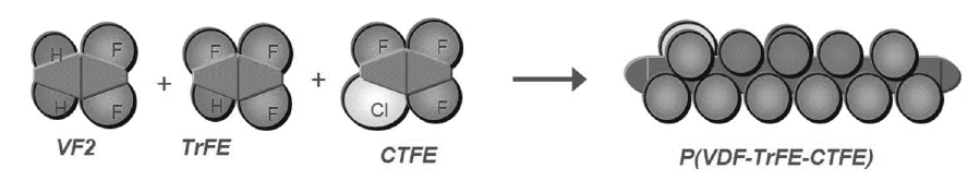
This type of EAP typically requires a large actuation voltage to produce high electric fields (hundreds to thousands of volts) [36]. Examples of dielectric EAPs are electrostrictive polymers and piezoelectric elastomers, odd-numbered nylons (with an odd number of carbon atoms between amide groups) and polyurethane. One of the most studied dielectric EAP materials are piezoelectric polymers. Some example of this product are polyvinylidene fluoride (PVDF), poly(vinylidene fluorideco-trifluoroethylene) (PVDF–TrFE) (Fig.1) and polyvinyl fluoride (PVF) and each material presents specific properties based on the chemical structure. For examples, poly(vinylidene fluoride) (PVDF), polyamides, parylene-C are semicrystalline while polyimide, polyvinylidene chloride (PVDC) are amorphous piezoelectric materials.
The first type arranges positively and negatively charged ions in crystalline form when an electric field is applied. The latter type contains molecular dipoles in its molecular structure, the dipole of this polymer is aligned when electric field is applied above a glass transition temperature which results in higher coupling factors and increased dielectric constants, with a controllable mechanical flexibility.
KEMER ACTUATOR DESIGN & INTEGRATION
KEMET Film Flex Assembled Actuator
Inspired by the idea to make the world a better, safer and more connected place to live, inventors are the ones who push the boundaries of innovation and create new devices towards these goals. KEMET’s latest piezoelectric polymer haptic actuator is one such invention. This new class of haptic actuator uses Electro-Active Polymer (EAP) technology, which is paper-thin at 150 μm thickness, featherweight and can easily mimic real-world stimuli for inducing haptic effect sensations. The working principle of these devices relies on implementation of a unique electro-active polymer, which when activated by means of electric field, realigns its molecules in a direction that elongates the film, creating in this way a piezoelectric effect that can effortlessly convey specific material textures and familiar feelings, like the clicks and clacks of buttons, and more. The technology and the applications for this kind of product, with a more nuanced, localized, natural-feeling experience than previous haptic devices, are endless. Bonding or framing the actuator to a rigid substrate transforms actuator elongation into an out-of-plane vibration, creating the haptic effect.
The wide bandwidth of the devices coupled with some physiology of touch and sensation allows for a very innovative haptic response rather than the simple on/off, buzz, or no buzz notifications associated with ERMs.
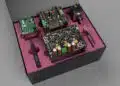
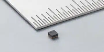
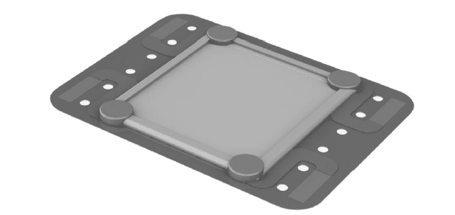
KEMET haptic actuator is built through the same manufacturing process as the film capacitors and this allow to get the best from the polymer film properties described above. The dimensions of the first launched KEMET haptic actuator are L=10mm, W=11mm, T=110um. This is expected to be the first haptic actuator of a family whose dimensions can vary depending on the market needs either in terms of performances and dimensions. The easiest way to take advantage of the haptic effect, produced by the KEMET haptic actuator when the electric field is applied, is to constrain it within a flexible surface: in this way, the alignment of the molecular dipoles within the film may be perceived as an out of plane displacement, depending on the frequency and amplitude of the applied electrical field. A flexible printed circuit board (flex PCB) has been used for that purpose, with a layout aimed at allowing wiring and fixing of the final Film Flex Assembled Actuator underneath the target surfaces (Fig. 2).
Integration of KEMET Film Flex Assembled Actuator in a finished product
KEMET actuators, unlike LRAs and ERMs, do not shake the entire device, can be embedded directly into a product’s surface and act as a haptic skin for devices. They are capable of providing localized and meaningful haptic feedback and enhancing the user experience, increase immersion and satisfaction. Because the integrated haptic devices vibrate over a wide range of frequencies, the user experience is enhanced. Rich, low frequencies provide pleasant sensations, and then higher frequencies impart the detail and overtones, creating effects with unusually natural sensations [37].
Mechanical integration of KEMET Film Flex Assembled Actuator is possible within both rigid shapes and flexible surfaces or volumes. The performances of the actuator are transferred to the user depending of its installation, positioning and material interface (also referred as “cover” in the following), so it is important to develop the structure of the final geometry around the FFAA depending of the needs of the users and application. Positioning the FFAA near the user facing surface, on the flex PCB side the stronger haptic effect will be achieved. Also the cover plays an important role in the modulation of perceived sensation. There are a variety of textiles and polymer blend sheets suitable and available in the market to be used as cover to guarantee good performances, safety and reliability of the final assembled product. Below are reported some of the most important characteristics (electrical insulation, resistance to bending, wear rate, waterproofness, conformability) that has to be considered for a cover material:
- Electrical insulation: surface cover material and cabling must fulfil electrical insulation requirements for an operating voltage ≥ 250Vac.
- Resistance to bending: the stiffness and thickness of the material used influence the capability to bend of the final product, the actuator’s energy transfer into a perceivable haptic sensation and the visibility of the FFAA on the cover surface. If the sheet is too flexible, a stiffener layer could be added as support on the PCB side where the actuator is assembled.
- Wear rate: scratch and wear resistance are important design factors for the user facing surfaces. Aesthetic characteristics must have the same requirements of standard products.
- Waterproofness: the whole integration of the haptic module should be waterproof. The FFAA is an electric device, so it has to be protected by water.
- Conformability: the user facing surface can also wrap around the whole integrated product part for seamless construction.
Considering some possible application of KEMET FFAA in different devices and technologies, in the next parts of the paper will be analysed the integration of the actuator with both hard and flexible shapes.
Hard shape integration
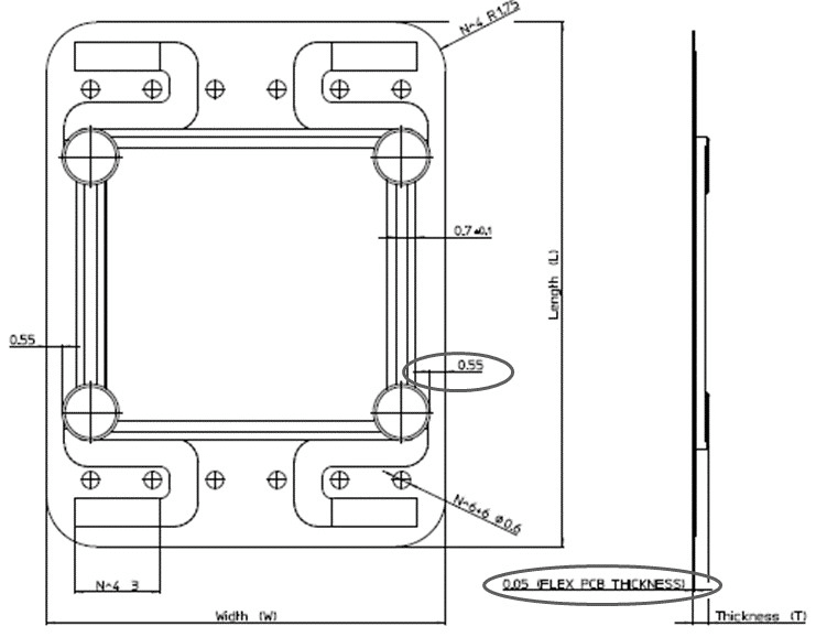
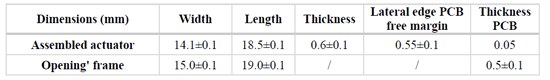
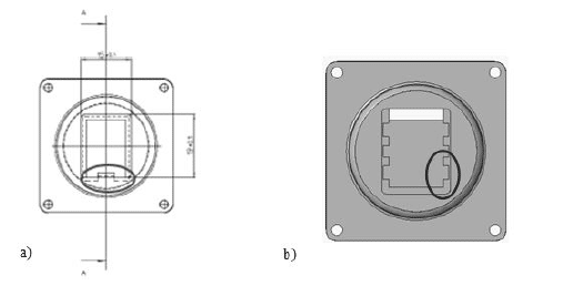
Hard shape integration is when the actuator has to be included within a rigid structure, various examples can be easily found in several human machine interfaces (buttons, joysticks, touch pad…). To allow proper haptic effect, the integration structure can be realized as the per next description. Considering the mechanical structure of the FFAA, with the active part in the centre of the flex PCB, to keep the best performances and to allow the right positioning of the soldering areas, the Film Flex Assembled Actuator should have a mechanical supporting structure working in the perimeter around the active part of the actuator (free margin of the flex PCB of the FFAA). Any rigid plastic, constituting the mechanical support of the FFAA, should be designed with the aim to avoid interference with the actuator, (active part of the FFAA) to prevent damages or stresses. On the contrary, any soft material such as foam can be used as substrate for the active part of the actuator to have light support, when working. When designing the FFAA mechanical support, the depth of the seat where the FFAA is placed, can be considered within the tolerance range of the FFAA itself (Fig. 3 and Table 1).
A high depth in the seat of the actuator may lead to an undesirable bending of the PCB surface with a modification or dampening of the haptic feedback. Another important aspect to be considered is the wiring. The overall design should allow the wires to easily pass thorough without applying any mechanical stress to the flex PCB and the overall FFAA. Finally, our suggestion from an aesthetical point of view, is that the external cover of mechanical support should be designed with the aim to create the best compromise between thickness and hardness to guarantee that the outline of the FFAA is not visible from the user side and that best haptic performances are preserved. Below will be discussed different examples of integration developed to integrate the FFAA in rigid mechanical support.
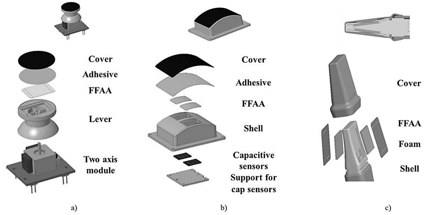
BUTTON SHELL
Button shell
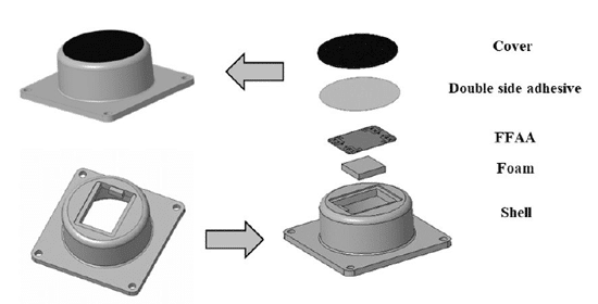
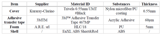
The first rigid support developed by KEMET was a round button, named Button shell. The construction and components disposition are reported in Fig. 4 while materials and layers thickness are listed in the Table 2.
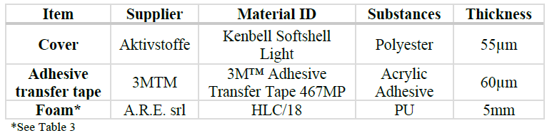
Foam
As discussed previously, in order to provide a light support to the FFAA when working, the active part of the FFAA can be supported by a thin foam layer placed below the actuator itself (Fig. 5). It can be integrated to the rigid part of the shell in several ways: the seat of the shell is designed with a rigid bottom or an external rigid support is placed in the cavity.
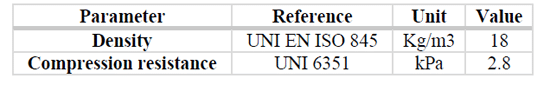
Independently by the support chosen, one important consideration that needs to be done in the design phase of the seat is that it needs to be big enough to allow the wires layout without constrains. In Table 3 are reported the main properties of the foam used in Button shell.
Soldering and wiring
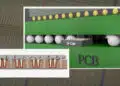
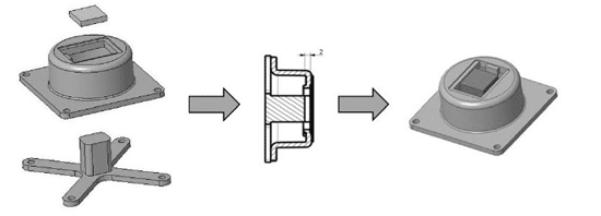
Another important aspect of the rigid shell design is the shape of the seat frame. The frame can be composed of a single tooth (Fig. 6a circled area) usable as a reference to facilitate the FFAA positioning near to the soldering area. A second design approach of the frame shape can be to add recesses on the edges (Fig. 6b) in order to hide the conductive paste drops at the four corners of the actuator assembly; this will be helpful with the target of obtaining a flat surface of the FFAA with the surface covering layer. Until now KEMET experience in wiring and final assembling of the FFAA into the fully integrated device, is fully manual. Therefore, it was observed that also the soldering of cables to the actuator plays an important role regarding mechanical stresses and potential failures. Examples of wires and soldering paste used in Button shape are reported in Table 4.
During assembly and later during handling of the FFAA, wires work as leverages towards the actuator. It could happen that during final assembly, just because of rough handling, the wiring can be partially disconnected from FFAA jeopardizing the overall manufacturing process. Moreover, stronger mechanical stresses can potentially affect the solder paste at the four corners of the actuator and therefore the film layers constituting the actuator. To avoid any mechanical stress on the FFAA due to wires, cable soldering can be performed both following the same plane of the Flex Assembled Actuator, or normal to it (Fig. 7). All the assembly and testing steps need to build the final integration shape shall be treated carefully, guaranteeing anyhow the easiest path to the driver connectors.
Double sided adhesive tape
Either heat activated or pressure sensitive adhesives can be used to attach the assembled actuators to the user facing surface. The choice depends on the shell material and on the user facing surface material. Heat activated adhesive should be avoided on the area where the actuator is since the bonding temperature must not exceed 100°C. Mechanical adhesion is easier compared to heat activated adhesion: it is suggested to avoid air bubbles within the adhesion area.
Surface cover
Cover should be chosen to avoid actuator performances reduction due to stiffness or thickness. Moreover, it has the following functions to be taken in consideration:
- to finish the user facing surface after the actuator positioning in the designated area
- to keep the FFAA in the designated position providing the mechanical constraints without affecting the vibration performances
- to guarantee electric shock and humidity protection.
Assembly procedure suggestions
The following suggestions for assembly are referred to the Button shell shape described above but are appropriate for the application of any general surface cover positioned on a rigid structure with a seat:
- Concerning the double-sided adhesive, both paper layers protecting the adhesive should pre-cut for an easy removal in the next steps. Moreover, to ease the surface cover positioning, the adhesive could be pre-assembled on the inner side of the cover (a paper layer will remain on the cover side intended for the adhesion on shell side). The cover should be placed with the exposed adhesive area on the edge of the shell. Then the paper layer should be removed while making the adhesive layer adhere to the shell (flex PCB side of the assembled actuator). The double side adhesive shall also be mechanically activated by gently pressing the cover to make it adhere, while also removing small air bubbles.
- During the assembly process the rigid shell could be hold steady (for instance in a vice).
- FFAA should be kept in the correct position into the shell adding a layer of adhesive Kapton between FFAA and the shell, paying attention to make it tight without air bubbles.
- It is good practice, at the end of the assembly, to test the assembled actuator for actuator activation, Capacitance and Insulation Resistance at HV.
Other integration ideas
Below are reported other three integration examples of KEMET FFAA in well know shape, specifically a joystick, a curved button and a mouthpiece. The structure of the different devices is depicted in Fig. 8.
Flexible shape integration
Since the main characteristics of the FFAA are its flexibility, conformability and localized haptic sensation, there might be soft structures, where it can be effectively used. Gloves and shirts are potential applications as soft and flexible shapes. Effective integration in soft shapes may be achieved following most of the suggestions and instructions given for the hard shapes. The easiest and smaller shape possible, requires just to cover the FFAA with proper surface cover and adhesive (both materials reported in this paper are suitable for the purpose) without any supporting mean and in this configuration, no foam layer is required. Wiring should be secured within the two layers of covers and the double sided adhesive and can be positioned directly on the soldering areas between FFAA and cables.
It is possible also to create a large shape or surface equipped with more than one FFAA, once the cable path and general architecture of the FFAA layout is defined, the main topic to be addressed is the mechanical fixing of FFAA to the designated area(s) and how to hide the wires. For both purposes, in KEMET integrated devices, the approach used to resolve the issue was to apply a small layer of foam between the two cover layers. Materials and layers thickness, used for the construction of flexible pads, are listed in the Table 5. Moreover, to hide and host the wires, tracks were carved on the foam with a laser engraver. The FFAA should be positioned on the top side of the foam with the actuator facing the foam (flex PCB substrate of the actuator visible). The wires should be placed on the rear side of the foam; therefore, the foam should be pre-cut to allow the wires to pass through.
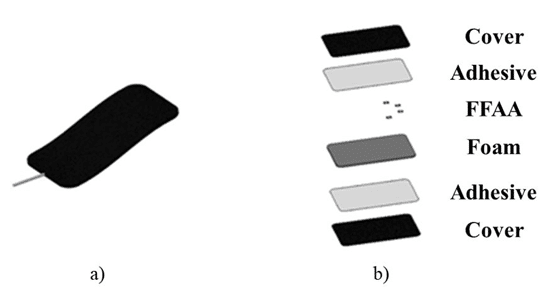
In case a multipolar cable is needed to connect several actuators to the power supply, a mechanical constraint, such as some Kapton strips, is needed to lock the cable to the foam and/or final cover. In Fig. 9 is reported the structure of a flexible and soft pad able to integrate one to four (and potentially more) actuators.
Effect design
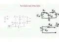
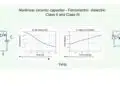
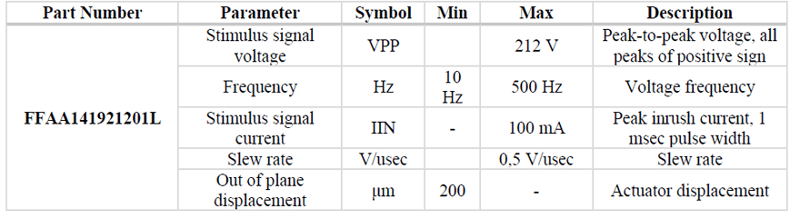
Haptic effects on the market are subject to the related technology. Each technology has its own frequency and amplitude range where the haptic effect can perform at its best. As indicated in the datasheet available in the KEMET Website, the Film Flex Assembled Actuator module can be driven by voltage waveforms with the characteristics reported in the following table.
Regardless the complex phenomenon which happens in the raw material when voltage is applied, the final effect of the Voltage waveform application is the vibration of the actuators, the haptic effect. The final outcome to the user depends not only on the waveforms but also on the individual perception. As previously reported, the most sensitive areas of human skin are located at the pads of our fingertips with a high sensitivity towards transient and oscillating external stimuli. The high sensitivity can detect a transient skin displacement on nanometer-scale, covering the frequency range from 20 Hz up to over 800 Hz, with a peak corresponding to 250 Hz.
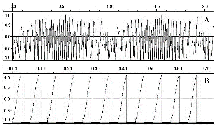
KEMET developed some waveforms to drive its FFAA and to show its capabilities through a Demo kit which provides an extensive multisensory user experience including touch, sound and sight stimuli. Voltage peak to peak values (around 200V) and frequency ranges (less than 200Hz) of the waveforms, which drive the KEMET FFAA, seem to be well aligned to the values identified in literature as suitable to be recognised as the stimuli for the human fingertips. Regardless the individual perception and sensitivity, peaks of the waveform are connected to the perception on the skin of the vibration, while frequency is associated to overall content to be transmitted.
Either waveforms with regular period or without a specific period have a meaning in the haptic simulation. Clock, heartbeat, and other periodic waveforms have been implemented as driving haptic effects for the FFAA and can be easily identified by the human fingertips. As well, some waveforms without a specific period, which has been developed to reproduce a kind of electric discharges or water movements (random waveforms), are still well identified by the human fingers; examples of both random and periodic waveforms are reported in Fig. 10. Some waveforms have been obtained adapting their equivalent sound waveforms. Sound effect might be reproduced by the FFAA; it can be reduced or avoided filtering frequencies above 200 Hz and tuning the overall waveform.
Regardless some hints on how to mimic the natural touch sensations through the waveforms building criteria, there will be as many waveforms as the vary many surfaces. Therefore, for any application some time should be spent in defining the best waveform (or set of waveforms) to get to the most natural fingertips response.
SUMMARY AND CONCLUSIONS
SUMMARY AND CONCLUSIONS
In the past century both analogic and digital electronics have made tremendous advancements realizing devices that could reproduce the objects, people, scenes, and experiences, through video, sound, and even touch. Today, we are witnessing how haptics as having a strong role in stimulating and developing research in bringing current technologies to a wider commercial market in the very near future.
Until now the training topics have been focused on advancements in materials science and engineering, but a growing interest in methods for designing and fabricating these materials into functional devices and systems is what will carry research in the years to come. Among the promising developments, Electro active polymer actuators are emerging due to their intrinsic properties such as flexibility, stretchability, transparency, and self-healing, paired with surprising haptic feedback capabilities. The flexibility and the versatility of EAP actuators, as reported in this paper, can lead to their application in an almost infinite number of applications and technologies.
Solutions to integrate KEMET Film Flex Assembled Actuator in both flexible and rigid shapes, surfaces and volumes have been presented and very interesting results that could lead to new devices development have been achieved. Even if the complete integration of this technology may still present numerous challenges, the active research in application fields such as mechanics, biomedical, VR/AR and computer science areas suggests that the currently large gap between actual technology and final application continue to shrink. This may lead to future haptic technologies that will attain widespread applications, with commensurately large implications for human society and economy.
REFERENCES
[1] M. Sreelakshmi, T. Subash, “Haptic Technology: A comprehensive review on its applications and future prospects,” Mater. Today Proc. 2017, 4, 4182–4187.
[2] S. Laycock, A. Day, “Recent Developments and Applications of Haptic Devices,” Comput. Graph. Forum 2003, 22, 117–132.
[3] A. Alur, P. Shrivastav, A. Jumde, “Haptic Technology: A Comprehensive Review of its Applications and Future Prospects,” (IJCSIT) International Journal of Computer Science and Information Technologies, Vol. 5 (5), 2014, 6039-6043.
[4] J. Song, J.H. Lim, M.H. Yun, “Finding the Latent Semantics of Haptic Interaction Research: A Systematic Literature Review of Haptic Interaction Using Content Analysis and Network Analysis,” Hum. Factors Ergon. Manuf. Serv. Ind. 2016, 26, 577–594.
[5] H. Seifi, F. Fazlollahi, M. Oppermann, J. Sastrillo, J. Ip, A. Agrawal, G. Park, K. Kuchenbecker, K. Maclean, “Haptipedia: Accelerating Haptic Device Discovery to Support Interaction and Engineering Design,” In Proceedings of the 2019 CHI Conference on Human Factors in Computing Systems (CHI ’19), Glasgow, UK, 4–9 May 2019; pp. 1–12.
[6] J.J. Berkley, “Haptic Devices,” Mimic Technologies Inc.: Seattle, WA, USA, 2003.
[7] M.A. Srinivasan, “What Is Haptics? Laboratory for Human and Machine Haptics,” Cambridge, MA, USA, 2001.
[8] X. Sun, K. Andersson, U. Sellgren, “Towards a Methodology for Multidisciplinary Design Optimization of Haptic Devices,” In Proceedings of the ASME 2015 International Design Engineering Technical Conferences and Computers and Information in Engineering Conference, Boston, MA, USA, 2–5 August 2015;
[9] H.Z. Tan, S. Choi, F.W.Y. Lau, F. Abnousi, “Methodology for Maximizing Information Transmission of Haptic Devices: A Survey,” Proc. IEEE 2020, 108, 945–965.
[10] S. Hsiao and J. Yau, “Neural basis of haptic perception,” in Human Haptic Perception: Basics and Applications, M. Grunwald, Ed. Basel: Birkhäuser Basel, 2008, pp. 103–112.
[11] R. S. Johansson and J. R. Flanagan, “Coding and use of tactile signals from the fingertips in object manipulation tasks,” Nat. Rev. Neurosci., vol. 10, no. 5, pp. 345–359, 2009, doi: 10.1038/nrn2621.
[12] J. A. McGrath and J. Uitto, “Anatomy and Organization of Human Skin,” Rook’s Textb. Dermatology Eighth Ed., vol. 1, pp. 34–86, 2010, doi: 10.1002/9781444317633.ch3.
[13] J. Dargahi and S. Najarian, “Human tactile perception as a standard for artificial tactile sensing—a review,” Int. J. Med. Robot. Comput. Assist. Surg., vol. 1, no. 1, pp. 23–35, Jun. 2004, doi: https://doi.org/10.1002/rcs.3.
[14] E. Kandel, J. Schwartz, “Principles of Neural Science,” Fifth Edit. Elsevier, 2013.
[15] V. Mountcastle, “The Sensory Hand: Neural Mechanisms of Somatic Sensation,” Harvard University Press, 2005.
[16] M. Nolano et al., “Quantification of myelinated endings and mechanoreceptors in human digital skin,” Ann. Neurol., vol. 54, no. 2, pp. 197–205, Aug. 2003, doi: https://doi.org/10.1002/ana.10615.
[17] A. W. Freeman and K. O. Johnson, “Cutaneous mechanoreceptors in macaque monkey: temporal discharge patterns evoked by vibration, and a receptor model,” J. Physiol., vol. 323, no. 1, pp. 21–41, Feb. 1982, doi: https://doi.org/10.1113/jphysiol.1982.sp014059.
[18] M. A. Muniak, S. Ray, S. S. Hsiao, J. F. Dammann, and S. J. Bensmaia, “The Neural Coding of Stimulus Intensity: Linking the Population Response of Mechanoreceptive Afferents with Psychophysical Behavior,” J. Neurosci., vol. 27, no. 43, pp. 11687 LP – 11699, Oct. 2007, doi: 10.1523/JNEUROSCI.1486-07.2007.
[19] J. Bell, S. Bolanowski, and M. H. Holmes, “The structure and function of pacinian corpuscles: A review,” Prog. Neurobiol., vol. 42, no. 1, pp. 79–128, 1994, doi: https://doi.org/10.1016/0301-0082(94)90022-1.
[20] N. Cauna, “Structure and origin of the capsule of Meissner’s corpuscle,” Anat. Rec., vol. 124, no. 1, pp. 77–93, Jan. 1956, doi: https://doi.org/10.1002/ar.1091240106.
[21] M. Paré, R. Elde, J. E. Mazurkiewicz, A. M. Smith, and F. L. Rice, “The Meissner Corpuscle Revised: A Multiafferented Mechanoreceptor with Nociceptor Immunochemical Properties,” J. Neurosci., vol. 21, no. 18, pp. 7236 LP – 7246, Sep. 2001, doi: 10.1523/JNEUROSCI.21-18-07236.2001.
[22] D. C. Pease and T. A. Quilliam, “ELECTRON MICROSCOPY OF THE PACINIAN CORPUSCLE ,” J. Biophys. Biochem. Cytol., vol. 3, no. 3, pp. 331–342, May 1957, doi: 10.1083/jcb.3.3.331.
[23] R. S. Johansson, “Tactile sensibility in the human hand: receptive field characteristics of mechanoreceptive units in the glabrous skin area.,” J. Physiol., vol. 281, no. 1, pp. 101–125, Aug. 1978, doi: https://doi.org/10.1113/jphysiol.1978.sp012411.
[24] A. B. Vallbo and R. S. Johansson, “Properties of cutaneous mechanoreceptors in the human hand related to touch sensation,” Hum. Neurobiol., vol. 3, no. 1, pp. 3–14, 1984.
[25] I. Birznieks, V. G. Macefield, G. Westling, and R. S. Johansson, “Slowly Adapting Mechanoreceptors in the Borders of the Human Fingernail Encode Fingertip Forces,” J. Neurosci., vol. 29, no. 29, pp. 9370 LP – 9379, Jul. 2009, doi: 10.1523/JNEUROSCI.0143-09.2009.
[26] M. Paré, C. Behets, and O. Cornu, “Paucity of presumptive ruffini corpuscles in the index finger pad of humans,” J. Comp. Neurol., vol. 456, no. 3, pp. 260–266, Feb. 2003, doi: https://doi.org/10.1002/cne.10519.
[27] B. D. Gynther, R. M. Vickery, and M. J. Rowe, “Responses of slowly adapting type II afferent fibres in cat hairy skin to vibrotactile stimuli.,” J. Physiol., vol. 458, no. 1, pp. 151–169, Dec. 1992, doi: https://doi.org/10.1113/jphysiol.1992.sp019411.
[28] S. Biswas and Y. Visell, “Haptic Perception, Mechanics, and Material Technologies for Virtual Reality,” Adv. Funct. Mater., vol. 2008186, pp. 1–16, 2021, doi: 10.1002/adfm.202008186.
[29] T.H. Yang, J.R. Kim, H. Jin, H. Gil, J.H. Koo, H.J. Kim, “Recent Advances and Opportunities of Active Materials
for Haptic Technologies in Virtual and Augmented Reality,” Adv. Funct. Mater. 2021, 2008831
[30] J. Tapson, J. Diaz, D. Sander, N. Gurari, E. Chicca, P. Pouliquen, R. Etienne-Cummings, “The Feeling of Color: A Haptic Feedback Device for the Visually Disabled,” IEEE 2008, 978-1-4244-2879-3/08
[31] B. Horan, S. Nahavandi, D. Creighton, E. Tunstel, “Fuzzy Haptic Augmentation for Telerobotic Stair Climbing,” IEEE 2007, 1-4244-0991-8/07/IEEE
[32] C. Basdogan, F. Giraud, V. Levesque, S. Choi, “A Review of Surface Haptics: Enabling Tactile Effects on Touch Surfaces,” IEEE Trans. Haptics 2020.
[33] D. Pyo, S. Ryu, K.-U. Kyung, S. Yun, D.-S. Kwon, “High-pressure endurable flexible tactile actuator based on microstructured dielectric elastomer,” Appl. Phys. Lett. 2018, 112, 061902.
[34] W. Chen, Z. Zhu, “Flexible Actuators, Handbook of Smart Textiles,” January 2015, pp.381-410
[35] R. Shankar, T.K. Ghoshcd, R.J. Spontak (2007), “Dielectric elastomers as next-generation polymeric actuators,” Soft Matter, 3: 1116–1129.
[36] T. Mirfakhrai, J.D.W. Madden, R.H. Baughman, “Polymer artificial muscles,” Materials today, 2007,10:30-38.
[37] KEMET, Piezoelectric Haptic Modules – Film Flex Assembled Actuators: https://content.kemet.com/datasheets/KEM_P0106_FFAA.pdf