


source: Electronic design article
The current-sense amplifier, which includes specialized features crafted to handle the most demanding applications, can play a key role in meeting efficiency goals for today’s power designs. Improving the efficiency of a power-supply design can yield many rewards. In a server farm, better efficiency translates into smaller size, reduced cooling costs, and a lower electricity bill. In a smartphone or tablet, it might mean shorter charging time or longer battery life. For both applications, the precise measurement of current plays a key role in boosting efficiency. This article will discuss how current measurement can improve performance, save power, and reap other benefits for power designs.
Overview of Precision Current Measurement
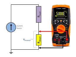
How do we determine the current flowing in a wire or trace? A common approach is to measure the voltage induced by the current across a shunt resistor. For the highest efficiency, a low resistor value of a few milliohms minimizes the power wasted as heat, but requires accurately measuring a voltage in the millivolt range.
In a power supply that uses digital control, the voltage typically is input to an analog-to-digital converter (ADC). Voltage in an analog design can be used to close a feedback loop.
It’s possible to measure this voltage with a standard op amp, or integrate the function into another building-block device. However, a dedicated current-sense amplifier (also called a current-shunt monitor) provides the highest overall performance.
Let’s compare these three options. Integrating the current-measurement function into a power-management device, for example, can reduce the cost and component count versus either an op amp or a dedicated current-sense amplifier. The integrated solution might therefore be the preferred choice in a cost-sensitive, space-constrained portable or wearable application. On the other hand, the performance is likely to suffer, since the silicon process is optimized for efficient power delivery, not precision analog measurement.
Choosing a standalone op amp certainly offers the designer a multitude of devices at various price points. However, the performance of the lowest-cost option probably falls short in two important specifications that directly affect measurement accuracy: input offset voltage (VOS) and gain error.
Many general-purpose op amps have VOS values ranging from 3 to 5 mV at room temperature. A VOS of 5 mV is equivalent to a 5% error when measuring a 100-mV signal across a shunt resistor. VOS is also temperature-dependent, varying by as much as 100 μV/°C, so a 50° temperature change can add up to 5 mV of offset, or an extra 5% measurement error.
A general-purpose op-amp circuit uses external resistors to form the gain network; mismatches between these resistors will create additional measurement uncertainty. Errors introduced by the resistive gain network are typically in the range of 2% (±1% resistors result in 2% mismatch). Resistor values are also temperature-dependent, with variations from tens of ppm/°C to hundreds of ppm/°C. A network of 200-ppm/°C resistors can add a 1% error over a 50° temperature change. More stable or more closely matched resistor networks are available, but at considerably higher cost.
Current-Sense Amplifier
To some extent, calibration can compensate, but some loss of precision is unavoidable. In total, the errors can amount to perhaps 10% over temperature. For applications requiring greater accuracy, there’s a better solution.
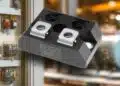
A voltage-output current-shunt monitor, also called a current-sense amplifier (Fig. 1), includes refinements that drastically reduce the aforementioned errors. The integration of four precision matched resistors reduces the maximum gain error to 1%, and the gain drift to 10 ppm/°C. VOS is lowered to 150 µV with a drift of 0.5 µV/°C. An external reference voltage connected to one of the internal resistors provides an offset to allow the measurement of bidirectional currents with a single-supply device.

1. This dedicated current-sense amplifier includes four precision matched resistors.
When measuring high-side signals, the small voltage across the shunt resistor often rides on a much larger common-mode voltage. A current-sense amplifier is designed so that the input common-mode voltage can swing much higher than the positive rail as well as below ground.
Texas Instruments offers a portfolio of current-sense amplifiers to suit different applications. The in Fig. 1 features a maximum gain error over temperature as low as ±1%, a choice of three gains, and a maximum quiescent current of 100 μA.
The is similar to the INA199, but has greater accuracy—a VOS of 35 μV, a maximum offset drift of 0.5 µV/°C, and a maximum gain error of 0.5%. The includes a high-speed comparator for fast detection of out-of-range conditions or short-circuit events. The integrates a 16-bit ADC with a I2C interface to provide a maximum VOS of 10 μV and a total gain error of 0.1%. Most devices offer the choice of several fixed gains.
For more information on current-measurement errors, read this . Now let’s examine the role of the current-sense amplifiers in a couple of applications.
Current Measurement in a DC-DC Switching Power Supply
Switching power supplies employ closed-loop feedback to provide stable, well-regulated power. A precision measurement pays dividends here—any errors can significantly degrade the regulation ability of the control system.

2. Several blocks in a dc-dc power supply can benefit from the precision of a current-sense amplifier.
The generic dc-dc converter block diagram in Figure 2 includes current-sense amplifiers in several areas:
- At the input, to measure input current and determine system power
- After the inductor as part of a current-mode feedback loop
- On the low side of a load
One current-sense amplifier that can fill multiple roles in a dc-dc converter design is the . The device features high accuracy over temperature, a high common-mode voltage range, high bandwidth of 400 kHz, and bidirectional current sensing capability. How does this match up with the application requirements?
Many industrial power distribution designs use a 48-V bus to power point-of-load (POL) dc-dc converters, so a high common-mode range on the input side is vital. The INA240’s maximum common-mode voltage of 80 V is more than adequate for a 48-V application, with sufficient headroom for power-rail transients.
After the inductor, common-mode voltage and bandwidth are important. The INA240 can handle a wide common-mode voltage range of −4 to 80 V, which is sufficient for many dc-dc applications. The part also features a bandwidth of 400 kHz and a common-mode rejection ratio (CMRR) of 132 dB (dc) and 93 dB (at 50 kHz).
Finally, a low VOS is the key parameter for low-side current measurements, because it enables the use of a smaller-value shunt resistor. This ensures that the ground voltage experienced at the low side of the load is as close to “true” ground as possible. The INA240 features a VOS(max) of ±25 μV, with a maximum drift of 250 nV/°C.
Precise Current Measurement in Battery Charging
Another application where precise current measurement can improve power-supply efficiency is battery charging. In such cases, increased efficiency translates into shorter charging time, which of course is a highly desirable feature. Lithium-ion has become the dominant battery chemistry in most rechargeable battery applications. Nonetheless, it imposes strict operating limits on voltage, current, and temperature to avoid undesirable consequences such as reduced battery life, internal short circuits, or even fire due to thermal runaway.

3. A Li-ion battery must follow a strict three-phase charging cycle to maximize available capacity and battery life. The allowable current during phases 1 and 2 is a function of C, the battery capacity.
Consequently, Li-ion requires a tightly controlled charging cycle, commonly known as the CC-CV (constant current-constant voltage) algorithm, as illustrated in Figure 3 for a single cell. There are three phases:
Pre-charge phase: A deeply discharged battery can’t accept the full charging current without overheating. A pre-conditioning phase applies a reduced current until the battery voltage has risen to a safe level.
Constant-current phase: During this phase, the battery is charged at a preset constant current that’s a function of the battery capacity C; the battery voltage gradually rises until it reaches 4.1 V or 4.2 V. The target value varies slightly depending on which particular Li-ion electrochemistry is being used.
Constant-voltage phase: The priority here is to prevent overcharging. With a constant voltage, the current gradually declines as the battery charge increases; the charging ends when the current declines to a preset termination value.
The task of the charger is to minimize charging time by charging the battery very close to the maximum allowable rate during each phase, while remaining within the safe operating envelope. To accomplish this, the charger design must be able to control both the voltage and current over the complete charging cycle, while monitoring the temperature.
The preferred “direct” or “fast charging” method uses a low-voltage/high-current strategy. This method employs an input voltage only slightly above the battery voltage, together with the ability to supply a high current directly to the battery. It enables high charging rates without exceeding temperature limits because there’s no voltage conversion at the device side to generate heat.

4. A battery charger consists of a wall-mounted ac-dc adapter and a device-mounted battery-management system.
Figure 4 shows a high-level block diagram of a charging system. It consists of two parts: an adapter that converts ac wall power to a dc voltage; and dc-dc circuitry in the device (smartphone, tablet, etc.) that charges the battery and monitors its condition. The power transfer and handshaking between the two units can be wired or wireless, depending on the application.
In addition to the current-sense amplifiers, the design incorporates two low-power microcontroller units (MCUs) and several power blocks. These include a switching power controller and transformer in the adapter, and the battery charger and battery fuel gauge in the device. TI offers a of battery-management products, the low-power microcontroller family, and to help with these functions.
The Role of Accurate Current Measurement in Battery Charging
Figure 5 includes two applications for precision current measurement. In the adapter, a current-sense amplifier monitors the adapter output current as part of the current-control feedback loop. In the device, a second current-sense amplifier monitors the charging current during the pre-charge and constant-current phases to minimize the overall charging cycle time.

5. The INA181’s 26-V common-mode voltage capability, plus an appropriate reference voltage, allows it to measure a Li-ion battery’s bidirectional high-side current flow.
Later, during normal device operation, the current-sense amplifier is also a key part of the “coulomb-counting” algorithm in the MCU. This algorithm tracks the flow of charge into and out of the battery by measuring the current every few milliseconds, and then calculates the remaining battery capacity.
TI offers several current-sense amplifiers for battery-charging applications, including the and for cost-optimized designs. This family of bidirectional, current-sense amplifiers can operate with common-mode input voltages from –0.2 to +26 V; the INAx181 family includes four fixed-gain options, from 20 to 200 V/V.
The INA181 has a bandwidth of 350 kHz—during the CC phase of battery charging, the loop response time is then quick enough to respond to fast current transients or ripples. The tighter tolerance increases charger efficiency by allowing the designer to specify a smaller guard band for battery protection and safety.
Conclusion
The precise measurement of current is a key component of a highly efficient power-supply design. Although simpler solutions exist, the current-sense amplifier is designed specifically for this purpose, and includes specialized features that make it the best choice for the most demanding applications.