Passive Components Blog
No Result
View All Result
  • Home
  • NewsFilter
    • All
    • Aerospace & Defence
    • Antenna
    • Applications
    • Automotive
    • Capacitors
    • Circuit Protection Devices
    • electro-mechanical news
    • Filters
    • Fuses
    • Inductors
    • Industrial
    • Integrated Passives
    • inter-connect news
    • Market & Supply Chain
    • Market Insights
    • Medical
    • Modelling and Simulation
    • New Materials & Supply
    • New Technologies
    • Non-linear Passives
    • Oscillators
    • Passive Sensors News
    • Resistors
    • RF & Microwave
    • Telecommunication
    • Weekly Digest

    Modelithics Releases Components Library v25.0 for Keysight 

    How to design a 60W Flyback Transformer

    Researchers Present Hybrid Supercapacitor Zn-Ion Microcapacitors

    Murata Releases 008004 High-Frequency SMD Chip Inductor

    Wk 19 Electronics Supply Chain Digest

    Bourns Extends Rotational Life Option for its Guitar Potentiometer

    Modeling and Simulation of Leakage Inductance

    Power Inductor Considerations for AI High Power Computing – Vishay Video

    TAIYO YUDEN Releases Compact SMD Power Inductors for Automotive Application

    Trending Tags

    • Ripple Current
    • RF
    • Leakage Current
    • Tantalum vs Ceramic
    • Snubber
    • Low ESR
    • Feedthrough
    • Derating
    • Dielectric Constant
    • New Products
    • Market Reports
  • VideoFilter
    • All
    • Antenna videos
    • Capacitor videos
    • Circuit Protection Video
    • Filter videos
    • Fuse videos
    • Inductor videos
    • Inter-Connect Video
    • Non-linear passives videos
    • Oscillator videos
    • Passive sensors videos
    • Resistor videos

    How to design a 60W Flyback Transformer

    Modeling and Simulation of Leakage Inductance

    Power Inductor Considerations for AI High Power Computing – Vishay Video

    Coupled Inductors in Multiphase Boost Converters

    VPG Demonstrates Precision Resistor in Cryogenic Conditions

    Comparison Testing of Chip Resistor Technologies Under High Vibration

    EMC Challenges for High Speed Signal Immunity and Low EMI

    MOSFET Gate Drive Resistors Power Losses

    Modified Magnetic Reluctance Equivalent Circuit and its Implications

    Trending Tags

    • Capacitors explained
    • Inductors explained
    • Resistors explained
    • Filters explained
    • Application Video Guidelines
    • EMC
    • New Products
    • Ripple Current
    • Simulation
    • Tantalum vs Ceramic
  • Knowledge Blog
  • Suppliers
    • Who is Who
  • Events
No Result
View All Result
Passive Components Blog
No Result
View All Result

PTC Current Limiting Protection Device Design With LTspice

18.12.2024
Reading Time: 11 mins read
A A

Ceramic disc PTC components are universally used for overcurrent circuit protection purposes. The principle of their function is relatively simple. Let’s look at the electrical resistance characteristic as a function of temperature (figure 1).

Figure 1
Figure 1

At a low temperature (normal voltage), the component’s electrical resistance is low, and in the case of a current surge, overvoltage, or external temperature increase, the component heats up. The electrical resistance value increases drastically once the component reaches a temperature known as the switch temperature (Ts).  This Ts is defined by the material used to manufacture the component and can be adjusted at will by a proper mix of oxides Ba(Sr, Pb)TiO3.

RelatedPosts

Modelithics Releases Components Library v25.0 for Keysight 

How to design a 60W Flyback Transformer

Researchers Present Hybrid Supercapacitor Zn-Ion Microcapacitors

Thus, at a low ambient temperature the PTC lets the normal current flow into the circuit, and above the Ts point it acts as an open circuit. However, in practice the phenomena underlying a PTC’s behavior are extremely complex and the equations describing them are seldom decipherable.

If you need to use a PTC in your application, there are two classic ways to explore. The first is the highly scientific way. For example, you might read articles about the Heywang model[1] and immerse yourself in the interesting principles of the grain boundary’s resistivity changes, coupled with the Curie temperature effect.

If you don’t have the time to dedicate to studying, the second approach is to go directly to a component’s datasheets. Be sure to look at Vishay’s document “PTC Explanation of Terms”[2], which describes the numerous PTC parameters, from Ts to the voltage dependent resistance (VDR) effect and trip and non-trip currents. All these characteristics will have to be considered for a high-performance design.

These two classic approaches are intellectually enriching, and they will challenge your engineering skills. Be sure that you have enough time though, because designing a PTC that works properly is a tricky job (we haven’t talked about analyzing the influence of all the aforementioned parameters’ tolerances).

So, one might wonder if there’s another method allowing for direct trial and error, a kind of plug-and-play approach that’s free, if that’s not too much to ask.
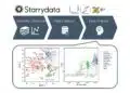
Enter LTspice.

When the SPICE models have been carefully conceived (which is normally a striving point for all specialists of electronic simulation models), they ARE in fact a faithful image of the specifications. Furthermore, they will combine all the modeled specification points at the same time into one simulation, showing all the interactions between them. The voltage-dependent effect, thermal mass, dissipation factor, ambient temperature effect, resistance variation as function of the temperature, trip and non-trip current — all the tolerances on all of these can be tested at the same time. There is no need for complex explanations. Simply select a component according to a common-sense guess and you can visualize the complex conduction phenomena during the simulations.

After researching the most popular simulation software, it appeared that the only software proposing electronic PTC modelling was TINA TI, but the components modeled were seriously outdated (PHILIPS Components became a part of Vishay years ago). Thus, no actualization was performed, and beyond that, no importable PTC model seemed to be available anywhere from any supplier — until now. The time was ripe to update overvoltage PTC modeling and I chose the fastest software available to do that: LTspice from Linear Technology. It was applied to the PTCTL (overvoltage protection), PTCCL (current limiter), and PTCEL (surge arrester) from Vishay.

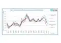
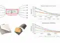
For the evidence, let’s look at the simulation in Figure 2. This small circuit illustrates the case of a PTC switching when an ac overvoltage of 800V at 50 Hz is applied to a Vishay PTCCL05H100SBE (R25 = 1600Ω) in series with a load with a resistance of 1,000W.  The simulation is repeated at three ambient temperatures. The current decreases in time as the PTC heats up, showing a shorter switching time when the ambient temperature increases. Look at the flattening of the current form with it approaches 0; this is the VDR effect. At low voltage, the apparent resistance of the PTC is higher.

Figure 2


Figure 2
Figure 3


Figure 3

A second simulation (figure 4) shows the function of the PTC as a resettable fuse. A voltage variable in time V(mains) is applied to another Vishay PTCEL (surge arrester). The three panes of Figure 4 show that as soon as the current into the PTC goes above a defined value (non-trip current of 120 mA), the PTC heats up and switches to high resistance values within a time dependent on its electrical resistance tolerance (Monte Carlo analysis). After 1,300s (arbitrary time), when the voltage comes back to 220V the PTC remains switched at a high resistance (middle pane) and the mains voltage needs to be tuned down to a low value (t = 1800s) to allow the PTC to cool down.

Figure 4


Figure 4
Figure 4


Figure 5

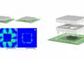
Now let’s more closely examine a ceramic PTC as an inrush current limiting device for on-board chargers (OBC), plug-in batteries for hybrid or electric vehicles, as well as power supplies for motor drives. In the example in Figure 6, the secondary winding of a three-phase transformer (ph1 to ph3) provides power to a load after voltage rectifying and smoothing by a DC-Link capacitor C1. For this simulation, the load (normally connected in parallel to C1) is not represented.

Figure 6


Figure 6

The design problem is in defining how many PTCs you need to place in parallel (two in Figure 6) to ensure than no PTC switches in normal conditions. In the case of a PTC switch, the voltage of capacitor C1 will never reach a value near the maximal swing of the ac source. Figure 7 shows the simulation of the voltage on C1 charging for three ambient temperatures (0°C, 25°C, and 50°C) with two (red curve), three (yellow curve), or four (white curves) PTCs in parallel. We see that there are problems with only two PTCs reaching the maximal voltage, especially when TEMP increases. Using three or even four will put the application on the safe side.

Figure 7


Figure 7

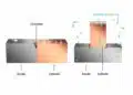
Using an electronic simulation allows for the hands-on testing of more combinations of PTCs in series and in parallel (as some suppliers recommend[3]). Figure 8 presents an example of a circuit with only one PTC (left side) in comparison with the same circuit with four PTCs (a network of two parallel branches of two PTCs in series) having the same average resistance but an enhanced thermal capacity. Figure 9 presents the simulation results of a circuit with one PTC (higher pane) and four PTCs (lower pane). We effectively see that the PTC network allows for the capacitor to charge at the top of the voltage swing while the single PTC tends to switch before this capacitor is charged.

Figure 8


Figure 8
Figure 9


Figure 9

Of course, because of the restricted number of PTC SPICE models available on the market at this moment, it’s not guaranteed that you’ll find the right component that meets all your expectations. In that case, don’t worry, the good old methods will always be applicable.

The generalization of SPICE PTC modeling has only just begun, and of course, Rome wasn’t built in a day, as the saying goes. It’s remarkable though that after more than 30 years of SPICE [R]evolution, one can still find component types without readily available accurate models. The PTC SPICE models presented in this article can be downloaded at https://www.vishay.com/docs/29184/ltspice_ptcel_cl_tl.zip.

The presented simulations can be obtained by email from [email protected].

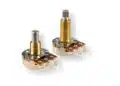
featured image credit: Vishay

References

  1. Sang-Hee Cho Journal of the Korean Ceramic Society
    1. Vol. 43, No. 11, pp. 673~679, 2006.
  2. https://www.vishay.com/docs/29007/ptcexpla.pdf, 2018, web
  3. https://en.tdk.eu/inf/55/db/PTC/PTC_ICL_OC_Leaded_260V_1000V.pdf, 2018

Related

Source: Sensors Online

Recent Posts

How to design a 60W Flyback Transformer

12.5.2025
10

Bourns Extends Rotational Life Option for its Guitar Potentiometer

9.5.2025
6

Modeling and Simulation of Leakage Inductance

9.5.2025
9

Murata and NIMS Built New Database of Dielectric Material Properties

5.5.2025
54

Tariffs Crush Sales Sentiment in April 2025 ECST Results

5.5.2025
70

Würth Elektronik Offers New Power Supplies Development Kit

29.4.2025
37

Shielding Cabinets

29.4.2025
20

Magnetic Shielding and Magnetic Shielding Sheets

29.4.2025
31

Characterization of 70GHz Thin Film Chip Resistors

26.4.2025
51

Corrosion its Development and Prevention

26.4.2025
25

Upcoming Events

May 14
11:00 - 12:00 CEST

Reliable RIGID.flex PCBs for Critical Applications – Made in Europe

May 14
17:00 - 17:30 CEST

Calculating Foil Winding Losses with AI

May 28
16:00 - 17:00 CEST

Power Over Data Line

View Calendar

Popular Posts

  • Buck Converter Design and Calculation

    0 shares
    Share 0 Tweet 0
  • Boost Converter Design and Calculation

    0 shares
    Share 0 Tweet 0
  • SEPIC Converter Design and Calculation

    0 shares
    Share 0 Tweet 0
  • What is a Dielectric Constant and DF of Plastic Materials?

    4 shares
    Share 4 Tweet 0
  • Flyback Converter Design and Calculation

    0 shares
    Share 0 Tweet 0
  • LLC Resonant Converter Design and Calculation

    0 shares
    Share 0 Tweet 0
  • Flying Capacitors Explained

    0 shares
    Share 0 Tweet 0
  • Supercapacitors Emerge as a Promising Solution to AI-Induced Power Energy Spikes

    0 shares
    Share 0 Tweet 0
  • MLCC and Ceramic Capacitors

    0 shares
    Share 0 Tweet 0
  • Dual Active Bridge (DAB) Topology Explained

    0 shares
    Share 0 Tweet 0

Newsletter Subscription


Passive Components Blog

© EPCI - Leading Passive Components Educational and Information Site

  • Home
  • Privacy Policy
  • EPCI Membership & Advertisement
  • About

No Result
View All Result
  • Home
  • Knowledge Blog
  • Premium Suppliers

© EPCI - Leading Passive Components Educational and Information Site

This website uses cookies. By continuing to use this website you are giving consent to cookies being used. Visit our Privacy and Cookie Policy.
Go to mobile version