Passive Components Blog
No Result
View All Result
  • Home
  • NewsFilter
    • All
    • Aerospace & Defence
    • Antenna
    • Applications
    • Automotive
    • Capacitors
    • Circuit Protection Devices
    • electro-mechanical news
    • Filters
    • Fuses
    • Inductors
    • Industrial
    • Integrated Passives
    • inter-connect news
    • Market & Supply Chain
    • Market Insights
    • Medical
    • Modelling and Simulation
    • New Materials & Supply
    • New Technologies
    • Non-linear Passives
    • Oscillators
    • Passive Sensors News
    • Resistors
    • RF & Microwave
    • Telecommunication
    • Weekly Digest

    Modelithics Releases Components Library v25.0 for Keysight 

    How to design a 60W Flyback Transformer

    Researchers Present Hybrid Supercapacitor Zn-Ion Microcapacitors

    Murata Releases 008004 High-Frequency SMD Chip Inductor

    Wk 19 Electronics Supply Chain Digest

    Bourns Extends Rotational Life Option for its Guitar Potentiometer

    Modeling and Simulation of Leakage Inductance

    Power Inductor Considerations for AI High Power Computing – Vishay Video

    TAIYO YUDEN Releases Compact SMD Power Inductors for Automotive Application

    Trending Tags

    • Ripple Current
    • RF
    • Leakage Current
    • Tantalum vs Ceramic
    • Snubber
    • Low ESR
    • Feedthrough
    • Derating
    • Dielectric Constant
    • New Products
    • Market Reports
  • VideoFilter
    • All
    • Antenna videos
    • Capacitor videos
    • Circuit Protection Video
    • Filter videos
    • Fuse videos
    • Inductor videos
    • Inter-Connect Video
    • Non-linear passives videos
    • Oscillator videos
    • Passive sensors videos
    • Resistor videos

    How to design a 60W Flyback Transformer

    Modeling and Simulation of Leakage Inductance

    Power Inductor Considerations for AI High Power Computing – Vishay Video

    Coupled Inductors in Multiphase Boost Converters

    VPG Demonstrates Precision Resistor in Cryogenic Conditions

    Comparison Testing of Chip Resistor Technologies Under High Vibration

    EMC Challenges for High Speed Signal Immunity and Low EMI

    MOSFET Gate Drive Resistors Power Losses

    Modified Magnetic Reluctance Equivalent Circuit and its Implications

    Trending Tags

    • Capacitors explained
    • Inductors explained
    • Resistors explained
    • Filters explained
    • Application Video Guidelines
    • EMC
    • New Products
    • Ripple Current
    • Simulation
    • Tantalum vs Ceramic
  • Knowledge Blog
  • Suppliers
    • Who is Who
  • Events
No Result
View All Result
Passive Components Blog
No Result
View All Result

Bypass Capacitor Resonances

9.8.2018
Reading Time: 3 mins read
A A

Source: EDN article

Article by John Dunn -August 08, 2018 explaining bypass capacitor resonances considerations. 

RelatedPosts

Modelithics Releases Components Library v25.0 for Keysight 

How to design a 60W Flyback Transformer

Researchers Present Hybrid Supercapacitor Zn-Ion Microcapacitors

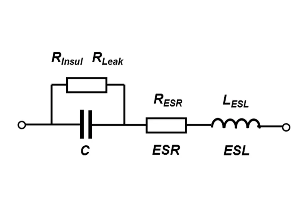
Ideal capacitors only exist in textbooks. Every real-world capacitor has additional complexity arising from its physical structure. Two plates separated by a dielectric layer are in series with wire leads or metal foils through which we make our actual connections. Those two metal conductors introduce an equivalent series inductance or ESL plus an equivalent series resistance or ESR. Taken all together, the physical capacitor is a series tank circuit that has a series resonant frequency and a “Q” of that series resonance which is affected by the series resistance.

It is not just a matter of semantics that a capaciTOR will exhibit an essentially capaciTIVE impedance for electrical excitation at any frequency below that of its series resonance and that it will exhibit an essentially inducTIVE impedance for electrical excitation at any frequency above that of its series resonance.

There is conventional wisdom for broadband rail voltage bypassing which says that you should use parallel combinations of different sized capacitors. The usual line-up is a large value of an aluminum or tantalum electrolytic capacitor, call that C1, in parallel with a large value ceramic capacitor, call that C2, in parallel with a small value ceramic capacitor, call that C3, in parallel with a circuit board’s artwork capacitance, call that C4, in parallel with heaven only knows what else such as harness capacitance and/or semiconductor device capacitance, call that C5.

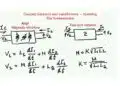
Always bear in mind that each of those five is not really just a capacitor. Each one is a series combination of a capacitor in series with an inductor in series with a resistor. Taken together, they comprise a series RLC circuit which will exhibit series resonance at a series resonant frequency or SRF where SRF = 1 / ( 2 * pi * sqrt (L * C) ). For a combination of five capacitors connected in parallel as described above, there will be five series resonant frequencies AND there will also be four parallel resonant frequencies which can be sketched as follows.

Figure 1 Nine Resonant Frequencies for Five Paralleled Capacitors

The four smaller capacitors C2 thru C5 get into parallel resonances at four frequencies that lie just slightly below their own series resonant frequencies. C1 however does not show any parallel resonance because that capacitor has nothing inductive with which to create a parallel resonant effect.

Using SPICE and some illustrative numbers, we can delve a bit deeper into the issue as follows.

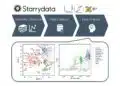
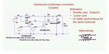
Figure 2 Parallel Bypassing in SPICE, Five Capacitors

For the five capacitances, there will be five series self-resonant frequencies, call them SRF1, SRF2, SRF3, SRF4 and SRF5. Each of the five capacitances will result in an impedance minimum at its own SRF, but, unavoidably, there will also be four parallel resonance peaks of the overall impedance at frequencies PRF2, PRF3, PRF4 and PRF5.

PRF2 arises from the capacitive impedance of the group of C2 thru C5 versus the inductive impedance of C1. Similarly, PRF3 arises similarly from the group of C3 thru C5 versus the pair of C1 and C2, PRF4 arises from the pair of C4 and C5 versus the group of C1 thru C3 and finally, PRF5 arises from C5 versus the group of C1 thru C4.

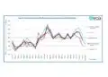
How deep the five impedance nulls will be and how sharply or broadly peaked the four impedance peaks will be is affected by the resistance values as seen below for just one example. Please note though that the parallel resonant frequencies themselves cannot be entirely eliminated. The parallel resonances will always be there, and you must account for that.

Figure 3 Impedance Curve Alteration by ESR

Note: This issue first came to my attention in a project where a parallel resonant frequency of some paralleled rail bypass capacitors turned out to be 16 MHz for a gate array that was clocking itself at 16 MHz.

What happened as a result is perhaps best left to the imagination.

Related

Recent Posts

How to design a 60W Flyback Transformer

12.5.2025
10

Researchers Present Hybrid Supercapacitor Zn-Ion Microcapacitors

12.5.2025
8

Modeling and Simulation of Leakage Inductance

9.5.2025
9

Supercapacitors Emerge as a Promising Solution to AI-Induced Power Energy Spikes

6.5.2025
69

Murata and NIMS Built New Database of Dielectric Material Properties

5.5.2025
54

Tariffs Crush Sales Sentiment in April 2025 ECST Results

5.5.2025
70

Solid State Polymer Multilayer Capacitors For High Temperature Application

2.5.2025
41

Graphene-Based BOSC Bank Of Supercapacitor Cells

2.5.2025
14

Hybrid Energy Storage System for Nanosatellite Applications

1.5.2025
9

COTS-Plus Bulk Tantalum Capacitor for LEO Flight Platforms

29.4.2025
39

Upcoming Events

May 14
11:00 - 12:00 CEST

Reliable RIGID.flex PCBs for Critical Applications – Made in Europe

May 14
17:00 - 17:30 CEST

Calculating Foil Winding Losses with AI

May 28
16:00 - 17:00 CEST

Power Over Data Line

View Calendar

Popular Posts

  • Buck Converter Design and Calculation

    0 shares
    Share 0 Tweet 0
  • Boost Converter Design and Calculation

    0 shares
    Share 0 Tweet 0
  • SEPIC Converter Design and Calculation

    0 shares
    Share 0 Tweet 0
  • What is a Dielectric Constant and DF of Plastic Materials?

    4 shares
    Share 4 Tweet 0
  • Flyback Converter Design and Calculation

    0 shares
    Share 0 Tweet 0
  • LLC Resonant Converter Design and Calculation

    0 shares
    Share 0 Tweet 0
  • Flying Capacitors Explained

    0 shares
    Share 0 Tweet 0
  • Supercapacitors Emerge as a Promising Solution to AI-Induced Power Energy Spikes

    0 shares
    Share 0 Tweet 0
  • MLCC and Ceramic Capacitors

    0 shares
    Share 0 Tweet 0
  • Dual Active Bridge (DAB) Topology Explained

    0 shares
    Share 0 Tweet 0

Newsletter Subscription


Passive Components Blog

© EPCI - Leading Passive Components Educational and Information Site

  • Home
  • Privacy Policy
  • EPCI Membership & Advertisement
  • About

No Result
View All Result
  • Home
  • Knowledge Blog
  • Premium Suppliers

© EPCI - Leading Passive Components Educational and Information Site

This website uses cookies. By continuing to use this website you are giving consent to cookies being used. Visit our Privacy and Cookie Policy.
Go to mobile version