


source: EDN article
Steve Sandler -June 27, 2017
Consider the measurement of a 100 nF ceramic capacitor. At 1 Hz, the capacitive reactance is approximately 1.6 MΩ. At series resonance, the equivalent series resistance (ESR) is typically about 10 mΩ. Accurately measuring this capacitor over a wide frequency range requires a dynamic range—the ratio of the capacitive impedance at the lowest frequency to the ESR at the low impedance—of at least 164 dB.

Choosing the right instrument
Few instruments, except for dedicated impedance analyzers, can support such a larger dynamic range. Using dedicated high-performance impedance analyzer might be a good choice if measuring these components is a major part of your job and you don’t have any budget constraints. Otherwise, it’s just probably not be a realistic option. A VNA is the next best thing. VNAs measure impedance and can display capacitance, inductance, real, imaginary, magnitude, etc.
A VNA can natively measure impedance using three different techniques. All three techniques are based on Scattering parameters (S-parameters). These three methods, along with the transformation from the S-parameters to impedance are shown in Table 1. Fortunately, these impedance transformations are generally built into the VNA, so you don’t need to do any of the calculations.
Table 1. Impedance and S-parameter transforms for VNA-based impedance measurement.

Each of these measurement techniques is accurate within a specific impedance range. The recommended range for each measurement is shown in Table 2.
Table 2. High fidelity measurement ranges of VNA-based impedance measurements.

These are recommended ranges and most VNA’s can do much better with careful instrument calibration just prior to performing the measurement.
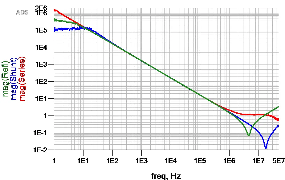
One of the most common decoupling capacitor values is 0.1 µF, which is why I selected a 0.1 µF low ESR ceramic capacitor to measure. I measured the sample capacitor using each of the three techniques using the OMICRON Lab Bode 100. Figure 2 shows the results. The measurements were directly exported from the Bode 100 VNA to Touchstone format where they were displayed simultaneously in a Keysight ADS data display. As you’ll see, the measurement techniques shown here can extend the Bode 100’s dynamic range.

Figure 1. Comparing the three VNA impedance techniques for a 100 nF ceramic capacitor.
All three methods are in very good agreement over the frequency range from about 100 Hz to 300 kHz, and they all performed much better than the recommended ranges. They also all diverge below 100 Hz and above 1 MHz. The 2-port Shunt Thru method is very accurate at low impedance magnitudes and so this technique results in a 10 mΩ impedance at resonance. The 2-port Series Thru measurement is very accurate for measuring impedance values and so it provides the correct impedance at 1 Hz, 1.6 MΩ in this example. The 1-port reflection measurement proves to be inaccurate at both the low impedance and high impedance ranges.Two measurement techniques that work
You can accurately measure the capacitor from 1 Hz to 50 MHz using two techniques that extend dynamic range. One is to use an impedance adapter, often available as an accessory for your VNA. The impedance adapter uses a resistor bridge to extend the dynamic range. The impedance adapter, shown connected to the VNA in Figure 2, has a recommended range of 20 mΩ at 1 Hz. At the resonance frequency of 20 MHz, the recommended minimum impedance measurement is about 6 Ω. At low frequency, the maximum recommended impedance is 600 kΩ.
 Figure 2. Impedance adapters connect to the Bode 100 to let you measure capacitance.
A second method is to insert a resistor between each VNA port. Figure 3 shows the device being measured in a “TEE” configuration. The impedance range for this method is modified by the selection of the series resistor. Figure 3. This Two port impedance measurement setup uses series resistors Reseries1 and Rseries2 in a “TEE” configuration.
The series resistors and the shunt capacitor are shown connected in Figure 4.
 Figure 4. Two-port impedance measurement with series resistors based on the schematic in Fig. 3
The capacitor was measured using both the impedance adapter and the 2-port shunt with series resistor methods. The measurements were directly exported from the Bode 100 VNA to Touchstone format where they were displayed simultaneously in a Keysight ADS data display as shown in Figure 5.
 Figure 5. The impedance adapter and the 2-port with series resistors both accurately measured the 100 nF capacitor from 1 Hz to 50 MHz including the 10 mΩ impedance at resonance.
Both methods accommodated the entire 164 dB dynamic range from 1.6 MΩ at 1 Hz to 10 mΩ at resonance. The 2-port with series resistors is slightly more accurate assessment at the 10 mΩ resonance. This is due in part to direct soldering the capacitor to a printed circuit board mount, eliminating the impedance adapter contact resistance variations between calibration and measurement. In any case, the impedance adapter far outperformed its specified performance of 6 Ω at 20 MHz and both methods provided very well over a very high dynamic range.
Comparing these two methods
Each of these two methods offers advantages and disadvantages. The impedance adapter is very easy to use and doesn’t require soldering the component to a printed circuit board mount. It also has a higher minimum impedance, requires short open and load calibration and the measurement range can’t be adjusted. The 2-port shunt with series resistors can be optimized for a specific range by selection of the series resistors. The method generally requires the component to be mounted to a circuit board for measurement.Conclusions
This article provided insight into the dynamic range and impedance ranges supported by the three native VNA impedance methods, 1-port, 2-port series and 2-port shunt thru. Two simple VNA methods were introduced that can be used to accurately measure the 164 dB dynamic range of a 100 nF ceramic capacitor. Additional information about these measurements and the devices used to perform them can be found in the references and at www.picotest.com.