


source: Vishay Intertechnology, Inc. ; ESA SPCD 2018 Symposium
EPCI e-symposium library article
The majority of tantalum capacitors used today are based on a solid electrolyte cathode system, and there have been many advancements in technology to enable smaller sizes, increased capacitance, and lower equivalent series resistance (ESR). Due to the relatively large market size and multiple suppliers, product improvements and new products are regularly reported and introduced to customers worldwide.
With a smaller and somewhat specialized market, the wet tantalum capacitor often does not get the same attention. Yet over the years, there have also been many changes in wet tantalum capacitor technology. Recent advancements have been made in both electrical and environmental performance, as well as mechanical form factor, to address new needs in ongoing applications, as well new applications in new markets. In this paper, I will review the advantages of wet tantalum capacitors, as well as the applications and new advances in technology.
published by EPCI under approval of ESA SPCD 2018 organizing committee.
Title: Advances in Wet Tantalum Capacitor Technology
Author(s): M. Mosier (1), J. Racine (2)
Organisation(s): (1) Vishay Intertechnology, Inc., 2813 West Road, Bennington, VT 05201 USA
(2) Vishay Intertechnology, Inc., 16 Daigle Lane, Suite 103, Sanford, ME 054073 USA
Symposium: ESA SPCD 2018
Reference: New Developments 4.
ISBN: N/A
e-Sessions Applications: Aerospace
e-Sessions Scope Components: Capacitors
e-Sessions Topics: Specification & Qualifications, Technology, Quality & Reliability
Today, tantalum electrolytic capacitors are used in a multitude of applications. By definition, a tantalum capacitor consists of a pellet of tantalum metal as an anode, covered by an insulating oxide layer that forms the dielectric, surrounded by a liquid or solid electrolyte as a cathode. Because of its very thin and relatively high permittivity dielectric layer, the tantalum capacitor distinguishes itself from other conventional and electrolytic capacitors in having high capacitance per volume (high volumetric efficiency) and lower weight. They are used in consumer, industrial, telecom, automotive, avionics, space, and medical applications [1].
Definition and Description
Wet electrolyte, sintered anode tantalum capacitors, often called wet slug tantalum capacitors, use a pellet of sintered tantalum powder to which a lead has been attached. Tantalum powder of suitable fineness, sometimes mixed with binding agents, is mechanically pressed into pellets. The lead is embedded during pressing of the pellet. The next step is a sintering operation in which binders, impurities, and contaminants are vaporized and the tantalum particles are sintered into a porous mass with a very large surface area.
A film of tantalum pentoxide is electrochemically formed on the surface areas of the fused tantalum particles. Provided sufficient time and current is available, the oxide will grow to a thickness determined by the applied voltage. The pellet is then inserted into a tantalum or silver can, which incorporates a cathode system that may consist of various metals. The liquid or “wet” electrolyte solution in the majority of wet tantalum capacitors is a sulfuric acid solution. A suitable end seal arrangement prevents the loss of the electrolyte [2].
Advantages
Wet tantalum capacitors have several advantages over solid tantalum, aluminum electrolytic, and ceramic capacitors. As with all other capacitors, these advantages lead to a very specific “sweet spot” or focused area of applications where the wet tantalum capacitor is the best and preferred choice. Wet tantalums require little derating and offer higher voltages (75 V, 100 V, and 125 V) than solid tantalums.
Rating for rating, wet tantalum capacitors tend to have as much as three times better capacitance / volume efficiency than aluminum electrolytic capacitors. Wet tantalums, with their hermetic case designs, have very long life and low DC leakage. Fig. 1 below shows where the wet tantalums falls within the capacitor families. As shown, they offer higher capacitance and voltage than solid tantalums, but smaller size than aluminum devices with the same rating.
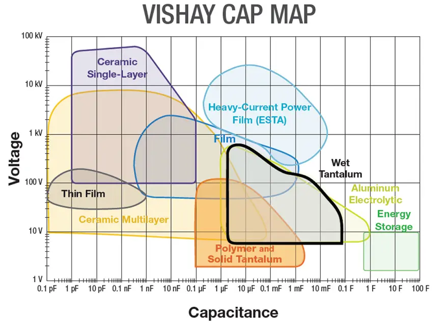
Fig. 1 Vishay Cap Map
Silver Case Axial
The initial wet tantalum capacitors were made of tantalum foil, upon which a Ta2O5 (tantalum pentoxide) dielectric was formed. The foil was then rolled into an anode section. The section was placed in a silver case, which was filled with an electrolyte and sealed by crimping a rubber or elastomer plug. The first tantalum capacitors were developed and introduced in the 1930’s. As with all tantalum capacitors, the base positive electrode is a pure tantalum anode. The wet tantalum design is in reality two capacitors in series. The internal anode and the case-cathode are separated by the liquid electrolyte. The negative case-cathode includes the case as well as an internal cathode, which can consist of many materials.
As applications required longer life, the hermetic seal silver case was developed. This was accomplished by soldering a metal top, which includes a glass to metal seal (GTMS) to the silver case. To maintain design consistency, the industry standardized all axial designs to four basic case sizes, which are still used today.

Fig. 2 – Photo of the four standard wet tantalum case sizes
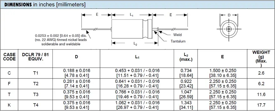
Table 1 – Wet Tantalum Case Dimensions
This wet tantalum design was now stable over long term exposure to temperature and rated voltage, and the first wet tantalum MIL specification for established reliability, MIL-C-39006, was initiated. The CLR65 (standard ratings), subsequent CLR69 (extended ratings), and CECC CT9 became the standards for AMS (avionics, military, and space) applications.
While axial silver case capacitors are still manufactured and used successfully today in several mature applications, they have posed a problem for the space community. Ultimately it was found that under minor reverse voltage conditions, silver particles from the case would attach themselves onto the anode surface, resulting in increased DC leakage. A new wet tantalum design was needed.
Tantalum Case Axial
In 1973, Sprague Electric Company was given NASA contract NAS8 -29819 for the Design, Development, Manufacture, and Qualification of Wet Slug All-Tantalum Capacitors. The purpose of the program was to develop a hermetically sealed all-tantalum capacitor capable of meeting the performance requirements of MIL-C-39006, but with the ability to withstand nominal reverse voltages and ripple currents.
The final report, which was issued in January of 1977, outlined the basic all-tantalum design, which is sold today as the Vishay 135D, 735D, CT79, and MIL-PRF-39006/22 series. With the advancements made by space exploration programs, the all-tantalum case wet tantalum capacitor became the industry standard for long life, high vibration, and reverse voltage capability [4].
Fig. 3 – All-tantalum case construction / cross-section
The M39006/22 (Style CLR79) design can withstand 3 V reverse voltage, up to ripple current, as well as 500 g mechanical shock, 80 g sine vibration, and 54 g random vibration. This new design was also able to withstand 500 thermal shocks from -55°C to +125°C. Subsequent testing of the M39006/22 (Style CLR79) tantalum case design achieved acceptable results when tested for radiation effects or exposure up to the 1000 krad.
While this technology was a breakthrough for AMS applications, it also allowed for the introduction of a high temperature (+200 °C) wet tantalum capacitor that became the standard for the oil exploration industry. With some adjustments in processing, the base design can operate for up to 2000 hours at +200°C and 60% of rated voltage. The high shock and vibration characteristics allowed the development and advancement of today’s measurement while drilling (MWD) tools.
While the all-tantalum case was now established as the industry-preferred standard, designers continued to request higher capacitance ratings. Initial gains were made by utilizing higher CV powders, which enabled the doubling of some capacitance values. The extended range MIL-PRF-39006/25 (Style CLR81) series was established. Subsequent requests were for lower ESR capacitors, which resulted in the Style CLR90 and CLR91 series, which are rated at half the maximum ESR of their CLR79 and CLR81 counterparts.
All Vishay M39006/22/25/30/31 capacitors are available with an “R” level failure rate of 0.01% per 1000 hours. Established reliability is initiated and maintained by ongoing life testing of samples to 10,000 hours at rated voltage and +85°C. The all-tantalum grade of capacitor has also proven itself stable in storage, as shown below.
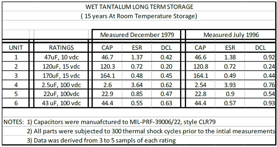
Table 2: CLR79 Long Term Storage Data [5]
Space Grade DLA Drawings
In 2006, Vishay worked with the US Defense Logistics Agency (DLA) and its space customers to develop four generic drawings for Group A and B screening of wet tantalum capacitors for space applications. The screening is equal on all four drawings (see Table 3). The DLA drawings are specific to each of the MIL-PRF-39006 styles.
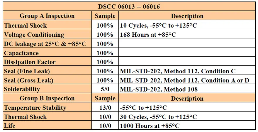 Table 3: DLA 0601x Screening
DLA 06013 covers only MIL-PRF-39006/22 (Style CLR79) ratings, to the extent that the MIL dash numbers are carried over to the specific DLA styles. For example, DLA 06013-0640H references an up-screened M39006/22-0640H (86uF, 10%, 100 V, T4 case, R failure rate, H vibration).
The other three drawings reference the subsequent MIL styles: DLA 06014 = M39006/25 (Style CLR81), DLA 06015 = M39006/30 (Style CLR90), and DLA 06016 = M39006/31 (Style CLR91). All drawings are specific that they offer MIL-PRF-39006/xx capacitors with additional test requirements for use in high reliability applications.
The SuperTan® Era
The quest for more capacitance continued. However, the current all-tantalum design with a tantalum anode and cathode was limited due to spacing within the case, as the distance between the anode and cathode got narrower. The next generation was going to need a technological breakthrough. In the end, it was a step back in time.
In 1991, Tansitor Electronics introduced the SuperTan, or ST, capacitor. The SuperTan utilized a deposited cathode on the tantalum case, similar to the old silver case designs. Instead of carbon or platinum, the ST cathode material was palladium. This thin wall cathode system represented a major breakthrough in tantalum electrolyte capacitor design (see Fig. 3).
The SuperTan design dramatically increased the available capacitance in each of the four standard case sizes (see Table 4). It provided two to three times more capacitance per unit volume, while substantially increasing ripple current capability and reducing ESR. Subsequently, other manufacturers developed processes utilizing niobium and ruthenium oxide to create their own extended capacitance all-tantalum wet tantalum designs. In 1993, Defense Electronics Supply Center (DESC) drawing 93026 was initiated. This drawing, now under DLA Land and Maritime control, is used in many avionics and military applications.
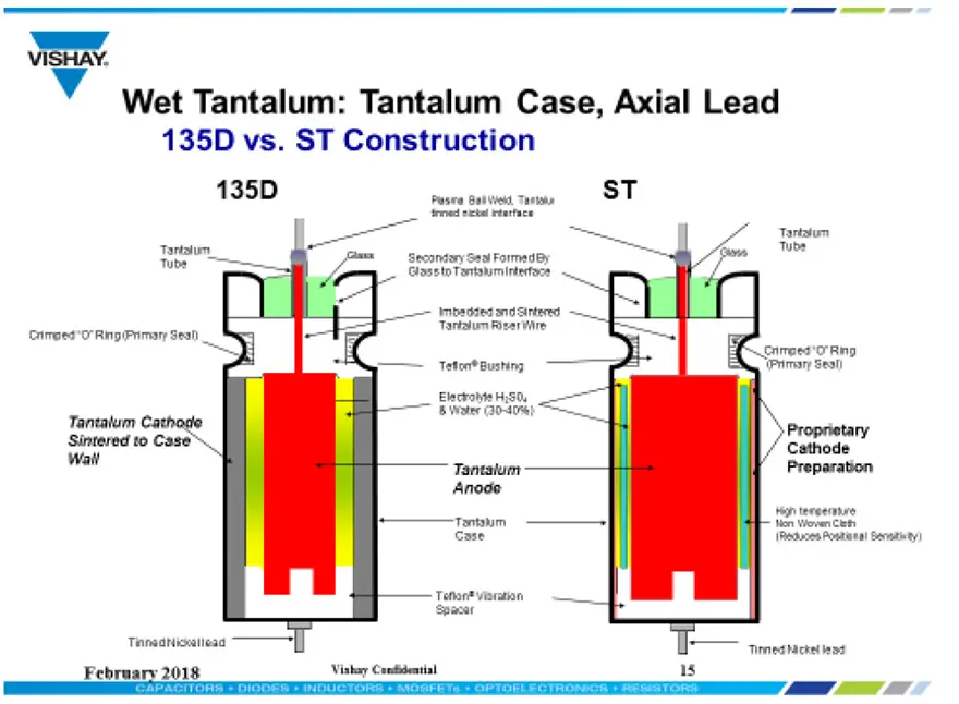
Fig. 3 Wet Tantalum Vishay 135D vs ST Construction Comparison
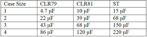
Table 4: Examples of 100 V Capacitance Extension with the ST
As with the all tantalum case, while the basic ST technology was focused on the larger AMS market, it eventually allowed for the introduction of a new T34 series of high temperature (+200°C) wet tantalum capacitors for the oil exploration market. The T34 provides stable capacitance and ESR over life, as well as high robustness in drilling and logging tools.
While the ST and DLA 93026 style is utilized in space applications, it was almost always under a customer specification or source control drawing (SCD), which outlined additional lot qualification or screening. This was due to the fact that the SuperTan style, which had a deposited cathode system, could not consistently withstand the high shock and random vibration needed for a space-level capacitor. As capacitance increased, there were trade-offs in performance, as shown in Fig. 4.
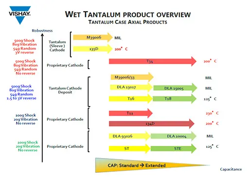
Fig. 4. Vishay Axial Case Wet Tantalum Overview
Vishay began development on a new series of all-tantalum wet tantalum capacitors in 2009. The goal was to be able to offer the extended capacitance ratings of the SuperTan type, with an established reliability failure rate and space-recognized “H” vibration level. The T16 series was released in 2010. It provides the exact capacitance values as the SuperTan type but utilizes a proprietary all-tantalum cathode system. This enables the T16 to consistently reach an intermediate level of mechanical performance at 100 g shock, 20 g sine vibration, and 27.78 g random.
In June 2013, DLA drawing 13017 was issued for the T16 series; subsequently, a poster presentation was given at SPCD in September 2013 [6]. As additional test data was collected, the T16 achieved approval to MIL-PRF-39006/33 in July 2014 for established reliability.
Fig. 5 – T16 series all-tantalum wet tantalum capacitors
With ongoing refinement of the design and process, Vishay initiated a request to update MIL-PRF-39006/33 in May 2018. The new revision would offer the full-characteristic “H” option: 500 g shock, 80 g sine, and 54 g random. It would also update the reverse voltage requirement to a full 3 V.
Concurrently with improvements in the T16’s mechanical performance, work continued to develop ultra-high capacitance ratings in the standard axial all-tantalum case. The T18 was released in 2013. Some capacitance examples are shown in Table 5.
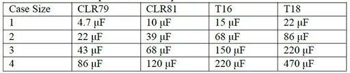
Table 5: Examples of 100 V Capacitance Extension with the T18
The T18 series was released using the same case-cathode as the T16. As a result, the T18 today is also capable of meeting the characteristic “H” mechanical performance (see Table 6).
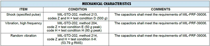
Table 6: T18 Mechanical Performance [7]
While advances in case-cathode technology have led to higher capacitance values, they have also allowed for the development of new case configurations, including large hybrid high energy capacitors, as well as a small surface-mount design.
Surface-Mount
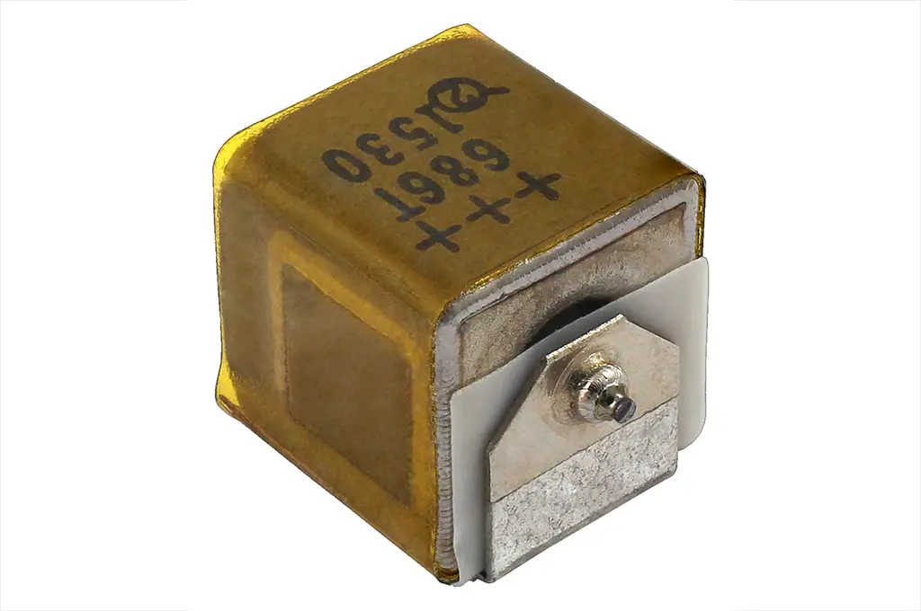
As the whole electronic component industry moved towards surface-mount technology, the wet tantalum capacitor had remained as an axial leaded device. The first early attempt to offer a surface-mountable wet tantalum capacitor was the Arcotronics SMTH. This was achieved by attaching special preformed SMD mounting tabs or terminations to the existing or standard axial tantalum case design. They could be manually soldered to the PCB using the tabs (see Fig. 6).
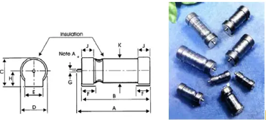
Fig. 6 – SMTH drawing and photograph [8]
The next generation of surface-mountable wet tantalums was the M35 series, developed by Vishay. The M35 features a molded style with terminations. The design incorporates a complete T1 axial all-tantalum wet tantalum capacitor, which is welded to a lead frame, then molded (see Fig. 7).
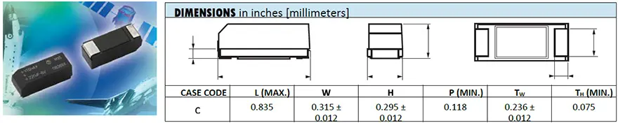 Fig. 7 – M35 series photo, drawing, and dimensions [9]
The new industry standard today is the T22 series from Vishay. It is the first true SMD wet tantalum capacitor. It has a hermetically sealed rectangular tantalum case with terminations and is available in either bulk or a reel pack option (see Fig. 8 below).
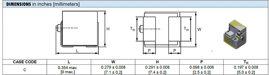
Fig. 8 – T22 wet tantalum capacitor cross-section and dimensions
The T22 is being used in several avionics applications today. Evaluation of the T22 series of capacitors by NASA, which included high temperature storage, seal testing, random vibration testing, accelerated life testing at +125ºC and rated voltage for 770 hours, and temperature cycling found that the design is robust enough for space applications. [11]
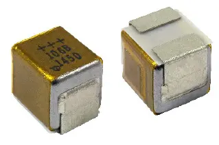 Fig. 9 – Vishay T22 wet tantalum
High Energy
For high energy or bulk power applications, several axial wet tantalum capacitors are often connected in parallel and / or series. While customers can do this on their printed circuit board (PCB), the capacitor manufacturer can also provide a pre-assembled module or array of capacitors. The original arrays were made of the silver case capacitors, and there was actually a full MIL-PRF-3965 specification.
While these arrays are still available today, the largest are custom assemblies made from tantalum case wet tantalum capacitors (see Fig. 10). These are made in a wide variety of case materials and configurations to meet customer-specified performance requirements and are available with many termination options. Capacitor assemblies made include balancing resistors, diodes, and other components as needed to meet customer needs.
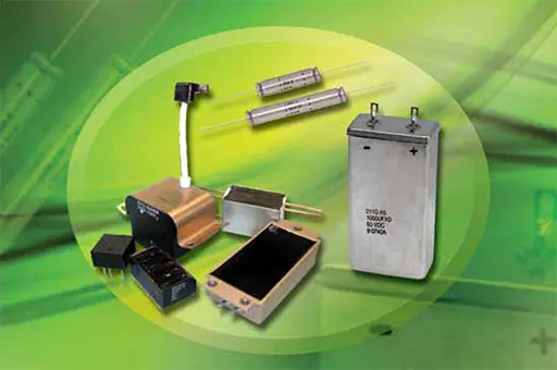
Fig. 10 – Wet tantalum capacitor assemblies
In some high energy or bulk power applications, the best solution may be the relatively new high energy, sometimes termed “hybrid,” wet tantalum capacitors. These capacitors utilize a tantalum anode and tantalum case, but need a hybrid cathode made by depositing a material such as ruthenium or palladium on a small piece of tantalum foil. These large case size wet tantalums reach capacitance values of over 72,000μF at 25V and are used in energy hold-up and pulse power applications.
Very specialized designs, made with titanium cases, a special electrolyte, and rated for high voltages, have been used in medical implantable ICD applications for over 20 years. An individual ICD capacitor may provide 400μF at 250V in the relatively stable environment of the human body at an ambient temperature of 37ºC.
Concurrently, the military version of the high energy capacitor was being developed and used. The original configuration was a cylindrical case with radial terminations, such as the Vishay HE5 series (Fig. 11).
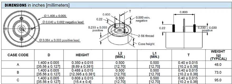
Fig. 11 – HE5 high energy wet tantalum capacitor
The A case high energy capacitor utilizes one anode, while the subsequent cases utilize two or three anodes in parallel connections to achieve the higher capacitance values. With the increase in anodes, the overall DC leakage increases, but the ESR declines, as shown in Table 7.
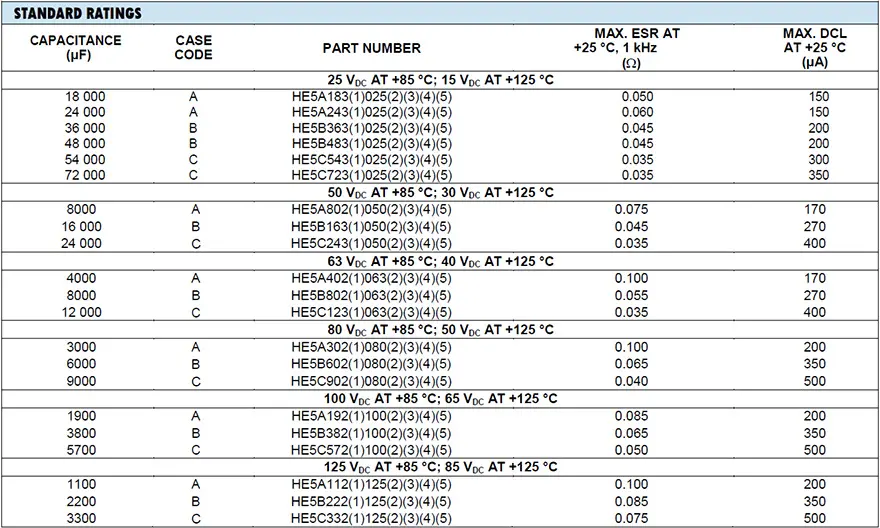 Table 7 – HE5 Standard Ratings
The newest designs, such as the Vishay EP1 series, offer a rectangular case with multiple termination and mounting options, including a surface-mountable design (see Fig. 12).
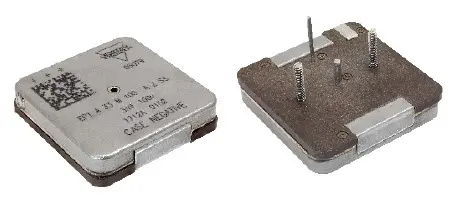
Fig. 12 – EP1 high energy capacitor
The rectangular case, with dimensions matching the 1.4 in or 35 mm diameter of the circular design (Fig. 13), allows higher capacitance values within a given case code (see Table 8).
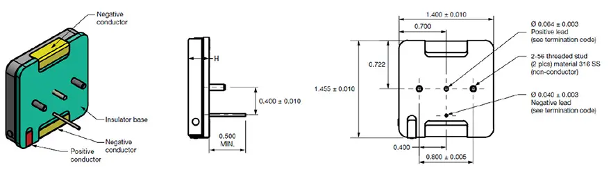
Fig. 13 – EP1 drawing and dimensions
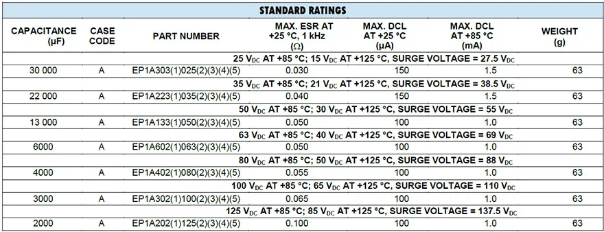
Table 8 – EP1 Standard Ratings [13]
The high energy capacitors are specified to many of the MIL-PRF-39006 electrical, environmental, and mechanical characteristics, as noted on the datasheets (see Table 9 and 10).
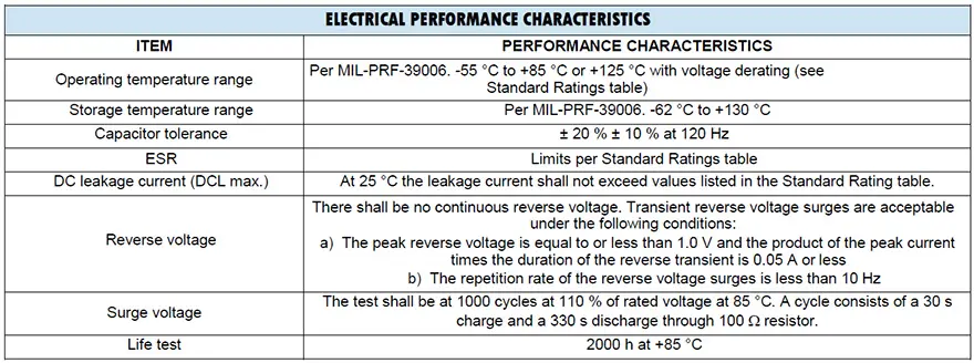
Table 9 – EP1 Electrical Performance
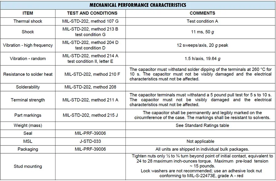
Table 10 – EP1 Mechanical Performance
All high energy capacitor ratings are qualified to a 2000 hour rated life test at +85°C (see Figure 14).
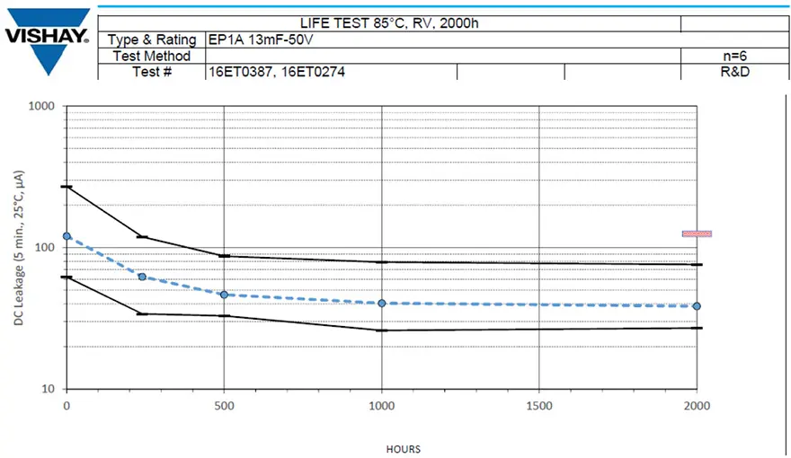
Fig.14 – EP1 life test example
Conclusion
Wet tantalum capacitors have been, and will continue to be, an important segment of the entire tantalum capacitor market. They provide high capacitance, low DCL, long life, and mechanical robustness. Characteristics that are not found with other alternatives when utilized within a given application. They continue to be used in many AMS applications and the demanding oil exploration sector.
Development and advancement in wet tantalum product performance will continue into the future to meet electronic designers’ needs. Advanced ultra-high capacitance axial leaded capacitors, such as the T16, are now approved to the demanding mechanical performance requirements of space applications. The T22 surface-mountable design has been proven robust enough for space applications. The high energy capacitors, such as the HE5 and EP1, provide the best solution for bulk capacitance, energy hold-up, and pulse power in AMS applications.
References
[1] Tantalum capacitor; Wikipedia; https://en.wikipedia.org/wiki/Tantalum_capacitor
[2] Wet Electrolyte Tantalum Capacitors; http://www.vishay.com/docs/40021/wetelecttantcapsbasics.pdf
[3] Vishay 135D datasheet; http://www.vishay.com/docs/40024/135d.pdf
[4] R. Maher, “Final Report on Design, Development, Manufacture and Qualification of Wet-Slug All Tantalum
Capacitors”, Sprague Electric Company, January 1977
[5] E. Fairfield, “CLR79 Storage Life”, Vishay engineering notebook, 1996
[6] M. Mosier, “High Performance Wet Tantalum Capacitors for Space Applications”, ESA SPCD 2013
[7] Vishay T18 datasheet; http://www.vishay.com/docs/40161/t18.pdf
[8] Arcotronics SMTH datasheet; Publication 5021, September 1996
[9] Vishay M35 datasheet; http://www.vishay.com/docs/40095/m35.pdf
[10] Vishay T22 datasheet; http://www.vishay.com/docs/40187/t22.pdf
[11] A. Teverovsky, “Evaluation of Series T22 Wet Tantalum Capacitors”, NASA/GSFC, 2017
[12] Vishay HE5 datasheet; http://www.vishay.com/docs/42104/he5.pdf
[13] Vishay EP1 datasheet; http://www.vishay.com/docs/42107/ep1.pdf
read the full technical paper in pdf here:
![]()
and presentation here:
![]()


