


In today’s world, nearly all electronic devices have wireless-connectivity features built into them, and they rely on transmitting and receiving RF or microwave signals from one device to another. Robert Meilleur from Corry Micronics in his article published by Microwaves & RF explains basics of EMI filtering by feedthrough ceramic capacitors and filters.
From laptop computers to home-security systems, the transmission and reception of RF or microwave signals from one device to another is crucial. The term used to identify the energy in these transmissions is electromagnetic radiation. Such radiation is around us everywhere, all the time, at frequencies ranging from 3 kHz to 300 GHz.
When electronic devices have internal operating processes that rely on signals in this RF frequency spectrum, unintended results may occur if the ever-present RF or microwave electromagnetic radiation interacts with the device. This occurrence is otherwise known as electromagnetic interference (EMI).
EMI is a serious concern for devices that are externally powered (ones that have a plug) or require signal wires that need to extend outside the device (signal wires that might attach to sensors or input/output devices). The wires that connect to power sources, or I/O points, can act as antennas that will allow EMI to be received (coupled onto them) and enter the device. Once inside the device, EMI can then cause the device to perform improperly.
The most common way to prevent EMI from interfering with these devices is by installing feedthrough filters on their signal and power lines.
Feedthrough Filters Defined
A feedthrough filter is a component that has a capacitive element built around a central conductor. Capacitors are reactive components, meaning they conduct electrical energy at different rates based on frequency. At very high frequencies, capacitors act like a short circuit, allowing RF energy to pass through them freely. At very low frequencies, they act like an open circuit, not allowing any RF energy to pass through them.
Since the capacitors are built around a center conductor that passes through the case and into the device, they’re often called low-pass filters. This is because they allow lower frequencies to enter the device with very little loss, while shunting high frequencies through the capacitors.
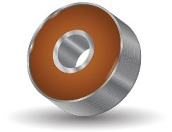
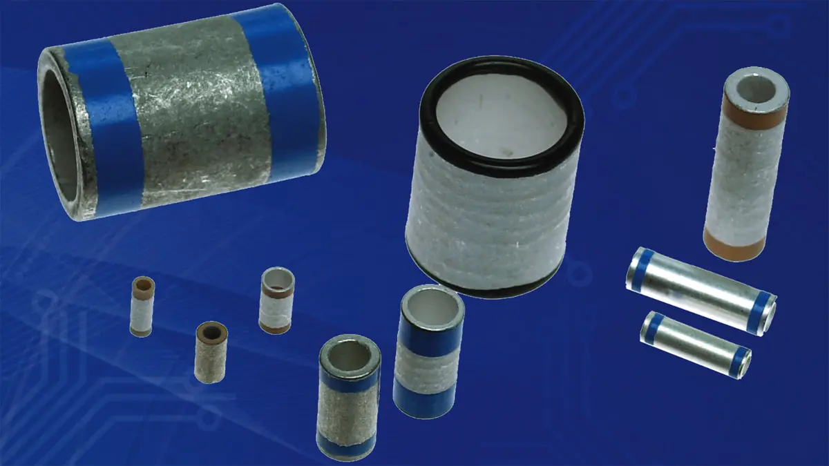
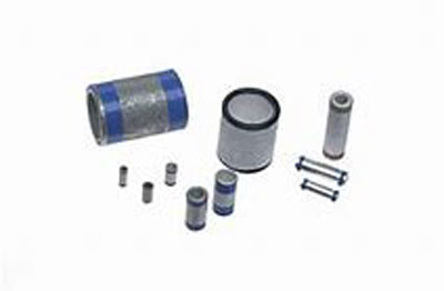
Feedthrough filters are built using a dielectric material that can be shaped into a circular form. This may be in the form of a discoidal (donut shape) or in a tubular form (Fig. 1). These shapes allow for the center conductor to pass through and attach to them in the center. This creates the “+” connection to the capacitor element. The outer diameter of this form is the “−” connection to the capacitor element, which is typically attached to an electrical ground point of the device.
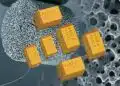
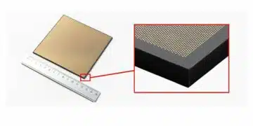
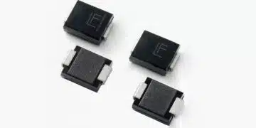
Many different types of material can be used to make the capacitor, but the most common material today is ceramic (Fig. 2). This is due to its ability to have relatively high dielectric constants and high working voltage capabilities.
Ceramic Feedthrough Filters: Basic Requirements
When reviewing the use of low-pass filters to prevent EMI, a few basic requirements are common to all applications:
- Cutoff frequency
- Insertion loss
- Power requirements
To incorporate a feedthrough filter into a design, you must be familiar with two sets of frequencies. The first set includes frequencies that the device utilizes internally for its operation. For example, if a switching power supply is used, the switching rate may be from a few hertz to over 2 MHz. The second set includes frequencies that will cause unintended operation of the device if it’s exposed to EMI. Typically, the interfering frequencies will be higher than those at which the device operates.
Cutoff Frequency
The cutoff frequency is the frequency at which the filter starts eliminating the unwanted EMI. This is defined as the frequency at which the filter removes 1⁄2 of the radiation energy level, or 3 dB, which is more commonly referred to as 3 dB of insertion loss.
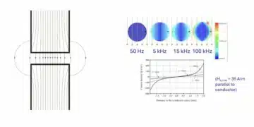
The cutoff frequency needs to be above the device’s operating frequencies, but it must also be low enough to eliminate as much of the higher frequencies as possible. Figure 3 shows a device that has internal operating frequencies of up to 300 kHz (see the green box). Within these frequencies, all I/O lines must be able to operate with minimal signal loss. The red box (above 300 kHz) represents frequencies that could potentially pose issues with EMI. For this device, the cutoff frequency was set at 1 MHz.
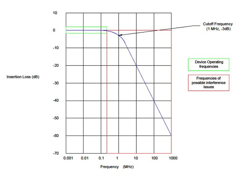 Fig. 3. The cutoff frequency needs to be above the operating frequencies of the device.
Insertion Loss
The term insertion loss refers to the filtering capabilities of the feedthrough filter at a given frequency. The MIL-STD-220 test standard is globally recognized for the characterization of these types of filters and their insertion-loss capabilities. Not all circuits are the same in terms of input or output impedance. This standard normalizes the measurement in a balanced 50-Ω test system.
When measured in this test system, the insertion loss of the feedthrough filter can be plotted versus frequency, which is normally shown on a log scale. Insertion loss is reported in decibels (dB). The formula for insertion loss is:
Insertion Loss = 10 Log10 (Pout / Pin)
where Pout = power level at the output of the filter, and Pin = power level at the input of the filter.
For every 3 dB of insertion loss, the power level of that frequency allowed through the filter and into the device is reduced by 50%. Common feedthrough filters today have insertion-loss values of 40 dB or more at 100 MHz. At 40 dB, the feedthrough filter is removing 99.99% of the RF energy.
Power Requirements
The other basic requirement when selecting the right feedthrough filter for your device involves the power requirements (voltage and current). The feedthrough filter must be able to operate at the input voltage of the device for power connections, or the signal voltage for signal lines. It also must have a center conductor that’s large enough to handle the current level required by the device. Most center conductors are made of copper; standard wire gauge amperage charts can be used for design purposes.
Ceramic Feedthrough Filters: Circuit Options
In feedthrough filtering, there are three common circuit types: “C”, “L”, and “π” (Pi). All three circuit types can be made with the discoidal or tubular type dielectrics mentioned earlier. Selecting the proper circuit for your device depends on the insertion-loss requirements (Fig. 4). First, set the proper cutoff frequency, and then determine how fast the optimal amount of insertion loss is needed after the cutoff frequency.
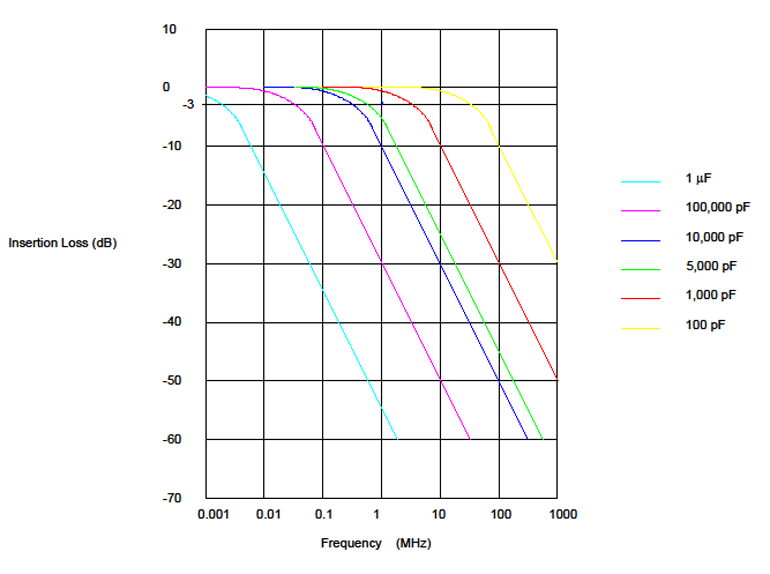 Fig. 4. The selection of the proper circuit for your device depends on the insertion-loss requirements.
Setting the Cutoff Frequency
For feedthrough filters, the cutoff frequency is mainly determined by a simple variable – the total capacitance of the filter. Typical design values for capacitance versus cutoff frequency are shown in Figure 5.
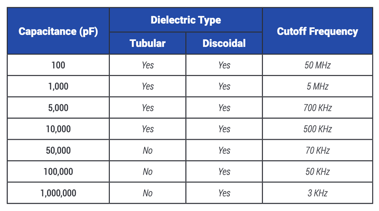 Fig. 5. The cutoff frequency is mainly determined by a simple variable.
Selecting the Circuit Type
A “C” circuit consists of a single feedthrough capacitor on a center conductor (Fig. 6). This circuit type will provide an insertion-loss slope after the cutoff frequency of approximately −20 dB per decade of frequency. However, as with all capacitors, there will be a point of self-resonance that will alter this slope. There will also be a frequency at which there will be a limit to the filter’s ability to provide any additional insertion loss. The typical industry-standard maximum stated insertion loss for “C” and the other two circuit types is around −70 dB.
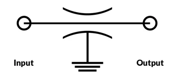 Fig. 6. A “C” circuit is comprised of a single feedthrough capacitor on a center conductor.
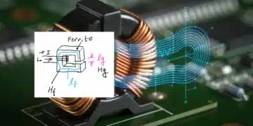
An “L” circuit adds an additional series of inductive elements to the “C” circuit (Fig. 7). These additional elements can be an inductive coil or a slip on a ferrite shielding bead over the central conductor. By adding one of these additional elements, the cutoff frequency stays the same, but the slope of insertion loss increases by another 20 dB per decade. Self-resonance will still be present at the same frequency as if this were a “C” circuit. The magnitude that the resonance will have on limiting the insertion loss will be diminished.
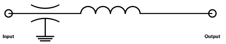 Fig.7. An “L” circuit adds an additional series of inductive elements to the “C” circuit.
A “π” (Pi) circuit is two “C” circuits separated by a series inductive element (same as an “L” circuit with an additional “C” circuit added after the inductive element) (Fig. 8). By adding this third element, the cutoff frequency stays the same, but the slope of insertion loss increases by another 20 dB per decade over the “L” circuit (to 60 dB per decade). This circuit type eliminates nearly all the effects of self-resonance on insertion loss (Fig. 9). For discoidal type dielectrics, this circuit type is made from three separate components. For tubular dielectric types, these are made with just two components, with both capacitors being made on a single dielectric tube.
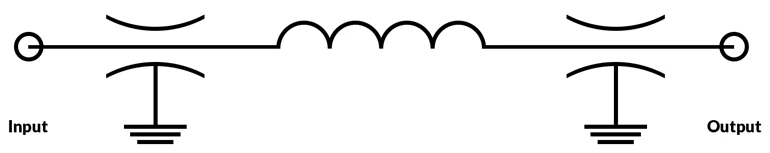 Fig.8. A “π” (Pi) circuit is two “C” circuits separated by a series of inductive elements.
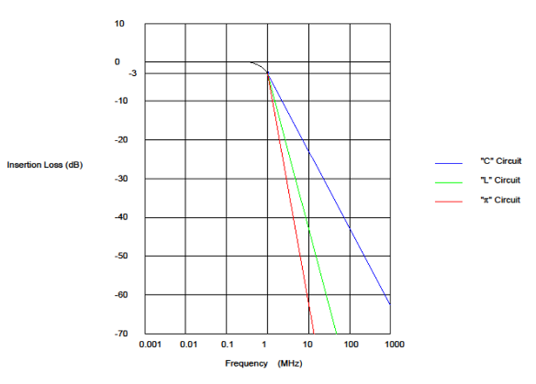 Fig. 9. These circuits all have different insertion-loss frequencies.
Ceramic Feedthrough Filters: Package Options
Ceramic feedthrough filters come in a variety of packages to suit the individual needs of different types of applications. These range from individual component types for single-line applications to multi-line products suited for applications that have many lines to protect against EMI.
Individual-Line Applications
Individual feedthrough filters are most commonly installed directly into the case of the device. This is done by either soldering the case of a solder-in type or bolting a bolt-in type directly into a threaded hole (or using a nut and lock washer in a clearance hole) on the case. Internally, the same installation methods can be used through partition walls or floor openings between device sections.
Figures 10-13 show the various package types for individual-line feedthrough filters. Figure 14 reveals their corresponding capacitance value, power ratings, and circuit types.
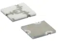
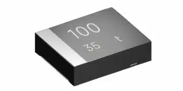
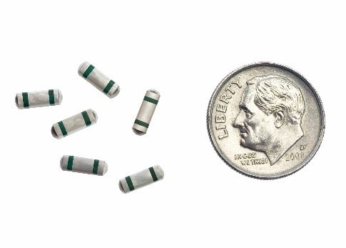 Fig. 10. SMT filters have a maximum capacitance of 8,200.
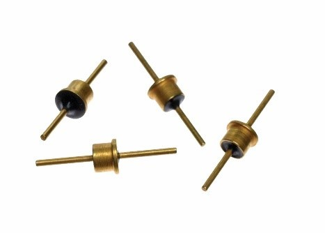 Fig. 11. Solder-in filters have a maximum capacitance of 50,000.
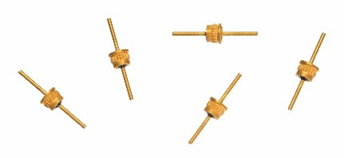 Fig. 12. Press-in filters have a maximum capacitance of 50,000.
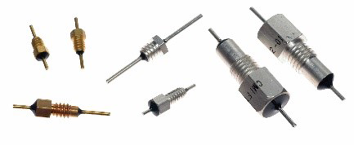 Fig. 13. The maximum capacitance of a bolt-style filter will vary depending on its VDC, power rating, and circuit type.
 Fig. 14. The maximum capacitance varies depending on the type of feedthrough filter you use.
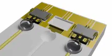
Multiple-Line Applications
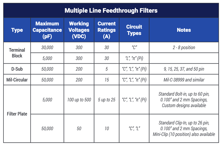 Fig. 15. When there’s a need to filter multiple I/O or power lines, multiple-line components are available.
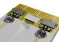
When there’s a need to filter multiple I/O or power lines, multiple-line components are available (Fig. 15). Terminal blocks, D-sub connectors, and mil-circular connectors are commonly used on case installations (Figs. 16-18). Filter pates are typically used for internal filtering on partition walls or floor openings between device sections (Fig. 19). These designs are all suited to match industry standard mating connectors and hardware.
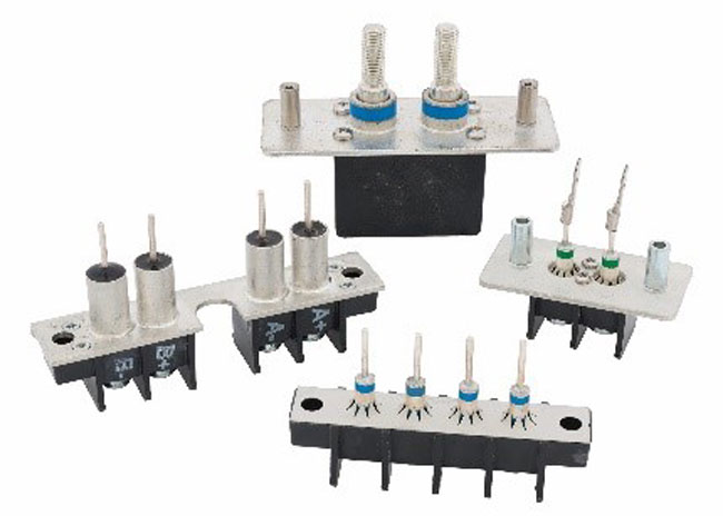 Fig. 16. The maximum capacitance of a terminal block will vary depending on its circuit type.
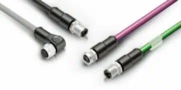
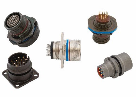 Fig. 17. Filtered mil-circular connectors have a maximum capacitance of 50,000.
 Fig. 18. D-sub connectors have a maximum capacitance of 50,000.
 Fig. 19. Filter plates have a maximum capacitance of either 30,000 or 5,000.