


Some of the “standard” parameters provided by the producers are not relevant in case of class II MLCCs. For these devices the designer must perform additional calculations and tests to select and to validate a class II MLCC for an application with given requirements. Variation of the main parameter (capacitance) due to usage conditions is so large that it behaves more as a transducer than as a capacitor. In some normal usage conditions the value of the capacitance drops even below 30 % of its nominal value. Could it be that the smallest and the largest value of capacitance (inside the nominal usage conditions) are the more relevant parameters?
Is it the time for a paradigm shift?
The paper was presented by Iosif Borcsa, Vitesco Technologies, Sibiu, Romania at the 3rd PCNS 7-10th September 2021, Milano, Italy as paper No.3.4.
LIMITATIONS AND APPLICABILITY
The author of this material doesn’t claim that the information presented in this material is exclusively true nor that it can or should be generalized.
The aim of this material is to present aspects regarding obtaining an accurate worst case value of the class II MLCCs and to propose an approach that would bring improvements.
The aspects related to the usage of class II MLCCs at high frequencies are not considered in this material. Some aspects related to class II MLCCs (like the effect of the DC bias) are expressed by different authors using different terms. In order to avoid any confusion, please see the explanations for the abbreviations and terms (after paragraph 5 – Conclusions) used in this material. These abbreviations and terms are written Italic in this material.
INTRODUCTION
The multilayer ceramic capacitors (MLCCs), are the most produced and used capacitors [1]. The reason for this is the high volumetric capacitance density, operating temperature range and low ESR. Class II MLCCs are used mainly where there is no need for a stable capacitance value nor high quality factor.
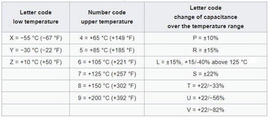
In the beginning of the manufacturing, due to thicker ceramic layers (>4 μm) and smaller electric field applied to the dielectric, the predominant variation of the capacitance (of the class II MLCCs) was due to the temperature. This is reflected in the most used code systems where the emphasis for classification is on the variation (of the capacitance) and on the usability (of the capacitors) according to the temperature, as it is in EIA RS-198 shown in Table 1.
The derating due to the DC bias was not considered, and not publicized.
The standard parameters related to the worst case value that are given generally for a class II MLCC in a specification sheet are:
- Nominal capacitance value
- Initial (capacitance value) tolerance
- Temperature behaviour
- Aging (of the capacitance value)
The worst case value of the class II MLCCs was mainly evaluated based on the initial tolerance, variation with temperature and aging.
In time, more knowledge was gained about different materials and recipes, technology allowed to achieve smaller parts, a higher precision, and a better control of manufacturing. This led to larger nominal capacitance or higher rated voltage values for the same size MLCCs. The increasing demand of class II MLCCs along with price pressure made many manufacturers consider downsizing the capacitors. This approach is quite tempting since with the same amount of materials (having a higher permittivity) and the same process, a significantly greater number of nominal capacitance MLCCs can be produced (at same rated voltage). At PCNS 2019 all present MLCC suppliers agreed that the downsized class II MLCCs have an increased derating due to the DC bias.
Although not quite standardized behaviour, the derating due to the DC bias became a big contributor to the global variation of the capacitance value.
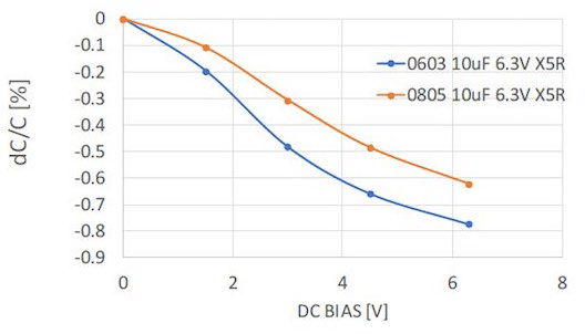
The fact the derating due to the DC bias can be quite different even for the MLCCs having the same temperature characteristic and from the same MLCC manufacturer makes this parameter hard to standardize. The shape of the curves is not even similar. The graph can have a predominant concave or convex shape. The magnitude of the derating too can vary significantly.
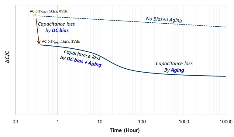
As if this additional contributing factor for variation was not enough, the effect due to the DC bias itself changes significantly in time. The DC bias derating is measured at 1 minute after the voltage is applied to the MLCC, but this doesn’t mean that after 1 minute the derating will remain constant in time. In fact, the value of the derating at 1 minute can be on a quite steep area of the characteristic. It is common not to have data about this variation in time of the DC bias (DC bias aging) in the specification sheets although this is the real “worst case” for the effect of the DC bias.
To determine the worst case value for the class II MLCCs it is necessary to know the DC bias aging. One possibility is to ask the manufacturer to provide it.
OPTIONS
Since the characteristic of the derating of the capacitance due to the DC bias (and it’s change in time) is dependent on the recipe, the materials used and on the knowledge of the technology, measurements must be done for each MLCC, for each voltage and temperature level. For this, equipment is needed, time and headcount must be invested (especially for the DC bias aging, where the interval for a measurement at one voltage level at room temperature is around 24 hours). To be statistically relevant a significant number of parts must be measured from each manufactured batch. This is a hard task for the manufacturers and an increase in the market price.
Some manufacturers are working on creating simulation tools that would simplify the process of providing such characteristics.
An option would be to include in the specification sheets the limits of the capacitance value (the smallest and largest value of the capacitance). In case of a 25 V, X7R type MLCC, these parameters would be the smallest and the largest value of the capacitance for all temperatures between -55 and +125°C combined with all DC bias levels between 0 and 25V and combined with the whole time interval between the soldering and 1000 hours after the soldering (if we don’t take into consideration the effect of the AC bias level). This type of approach is stated in IEC/EN 60384-9. Having these limits enables a safer design and an easier selection of the capacitors. Though this implies a big characterization effort, it doesn’t provide the worst case value (for each specific condition), only the extreme values. In different (and sometimes, even in the same) applications, the same manufacturer code MLCC can be used in quite different conditions (at different maximum voltage levels, at different maximum temperatures, …). If in all situations (for the worst case value) the smallest value of the capacitance (for the whole temperature and voltage range) would be used, in most of the cases, the margin for the capacitance value would be exaggerated and this would lead to higher prices and larger sizes.
PROPOSAL
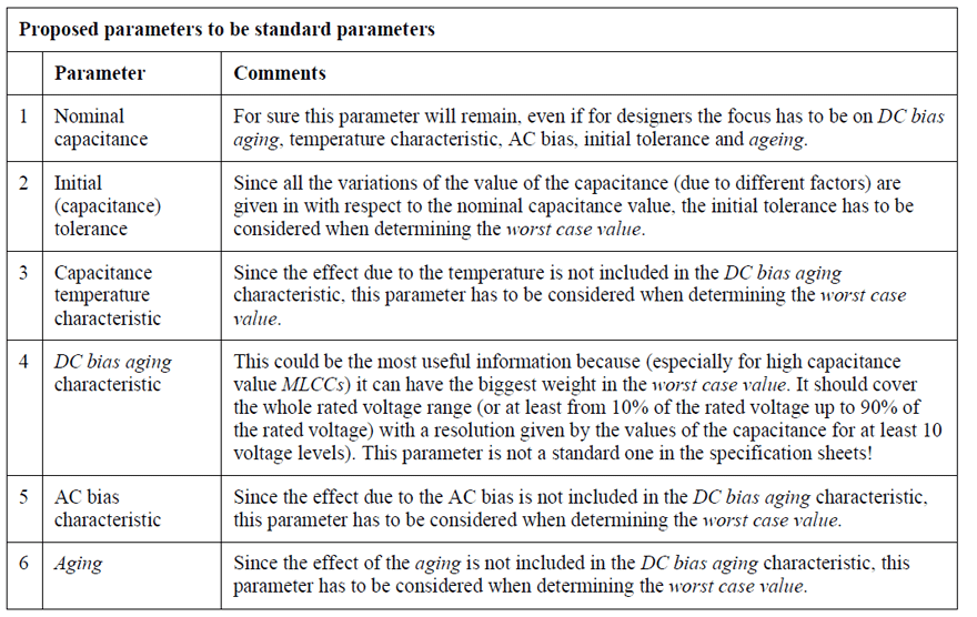
The proposal of the author is to include in the specification sheets, as a standard characteristic, the DC bias aging behavior (point 4 in the Table 2).
CONCLUSIONS
Obtaining the worst case value for class II MLCCs is not a simple task. Some of the provided characteristics (DC bias derating, DC bias after 24 hours for a voltage level, AC bias, the graphic temperature characteristic) are just typical, non-binding, unwarranted. This paper proposes an approach to enable manufacturers to provide more conclusive data.
The interdependencies of these parameters is complex and hard to predict with a good accuracy. Therefore, some producers don’t recommend a formula or a method to calculate the remaining capacitance value, instead they measure it for each specific case. Other producers recommend using the cumulative method.
Having the DC bias aging characteristic (not the nominal capacitance value) as a reference in evaluating the worst case value provides more accurate results.
If the market is not applying the proposed approach, there is risk of overdesign or malfunction.
ABBREVIATIONS AND TERMS
All abbreviations and terms described in this chapter are written Italic in this document.
Aging – The degradation (per decade of hours of the value of the capacitance) starting after 1000 hours after the last (un-biased) heating (above the Curie point). Not the same meaning in case of DC bias aging, where the “aging” (decreasing) of the capacitance value due to the DC bias takes place in a shorter interval (~ 24 hours at 25°C), as it can be seen in Figure 3, and is partially reversible when the DC bias is removed or decreased
Class II MLCC – if not stated differently in this material, it refers to class II as defined in EIA RS-198
DC bias aging – if not stated differently in this material, it means the effect (on the capacitance value) due to the DC (Direct Current) bias applied at room temperature and measured after 24 hours
DC bias derating (or derating due to the DC bias) – if not stated differently in this material, it means the effect (on the capacitance value) due to the DC (Direct Current) bias applied at room temperature and measured after 1 minute. Same as DC bias loss from Figure 1
Downsizing – (new) MLCCs having the same (compared to an older) nominal capacitance, same initial tolerance, same rated voltage, same temperature behavior, but smaller size
MLCC – Multi Layer Ceramic Capacitor
Worst case (value) – the “remaining” value of the capacitance for specific conditions after considering all the factors that can affect it (initial tolerance, temperature, DC bias aging, AC bias, aging)
REFERENCES
[1], [2] Wikipedia (https://en.wikipedia.org/wiki/Ceramic_capacitor)
[3] Tomas Zednicek, 2019 (https://epci.eu/high-cv-mlcc-dc-bias-and-ageing-capacitance-loss-explained/)
[4] Herb Te-Jen Ma, 2020 (https://www.electronicdesign.com/technologies/analog/article/21135733/diagnosing-class-ii-mlcc-effective-capacitance-and-aging-under-dc-bias)


