


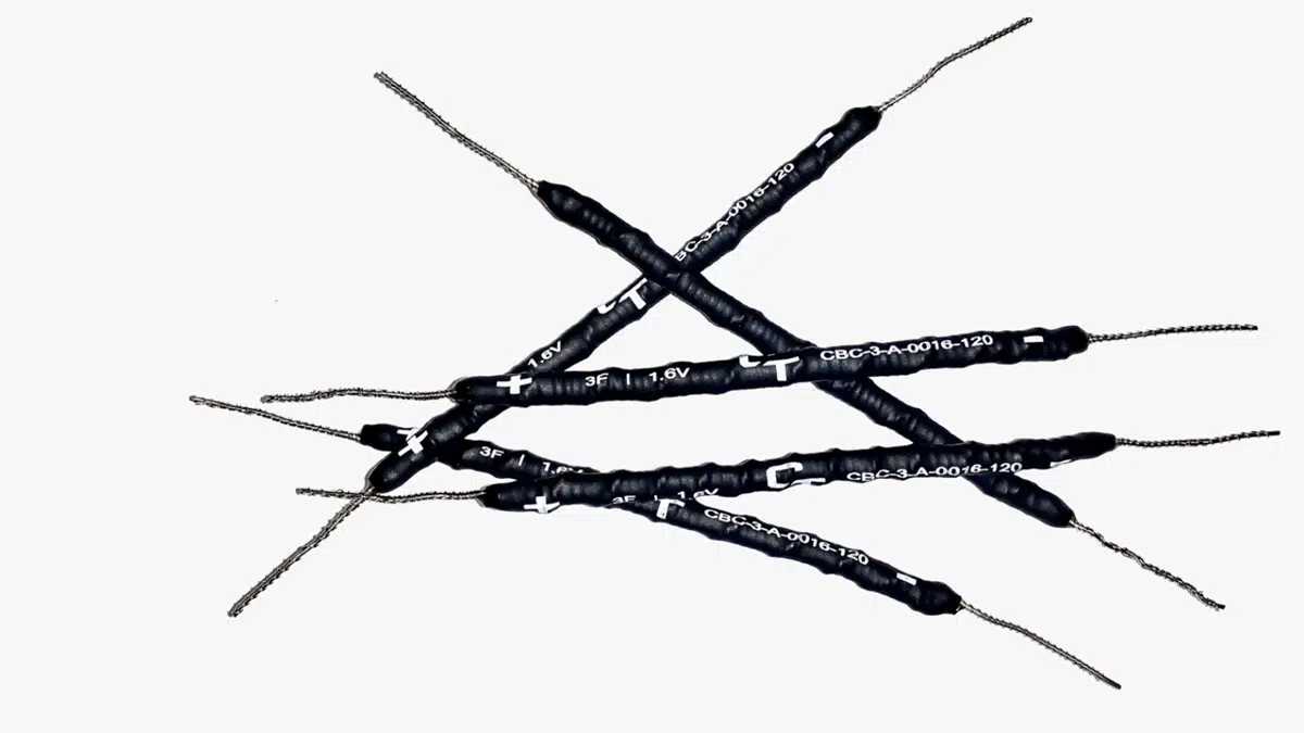
Capacitech Energy, Inc. is reimagining the energy storage industry by innovating the form factor that energy storage products come in. Initially focused on supercapacitors, the Cable-based Capacitor (CBC) product line, features a wire-like shape and is physically flexible, unlike traditional supercapacitors. Flexible supercapacitors can be used in applications in which they were never imagined, helping our customers achieve their design and performance goals.
Supercapacitors are energy storage components, like batteries are, but feature a different set of characteristics. Compared to batteries, supercapacitors have a superior cycle life, are capable of providing higher power bursts, and charge quickly among other unique characteristics.
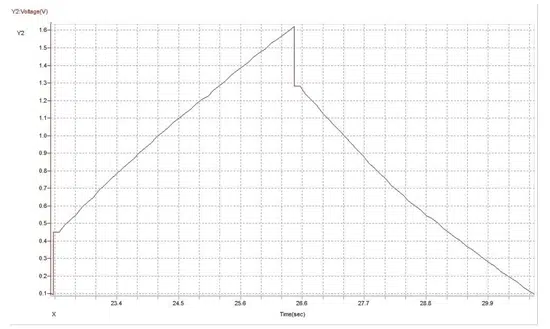
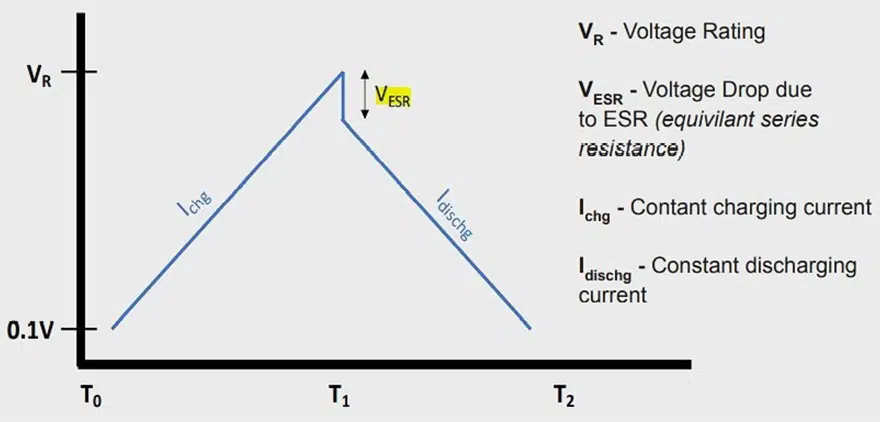
There are a few methods to evaluate a supercapacitor using testing equipment, such as a potentiostat. A common technique is to use a Galvanostatic Charge-Discharge (GCD) curve. A GCD curve is produced by charging and discharging the CBC with constant current to a specific voltage, as shown in Figure 1.
As current is applied, the voltage across the CBC steadily increases until a specific voltage is reached. In this case, the CBC is charged to 1.6V with 1.25A. Once the CBC reaches 1.6V, the CBC is then discharged to 0.1V with 1.25A. The capacitance and other important specifications can be calculated using the known charge/discharge current, voltage values, and time stamps recorded by the testing equipment.
Building Modules
Building flexible supercapacitor modules:
Individual cells of the CBC can be connected in series and parallel to meet the requirements of a given application (IoT devices, wearables, solar panels, power supplies, IT equipment, automotive, defense, etc…). This is a common practice in the supercapacitor industry, especially because a single supercapacitor typically has a voltage rating below 5V. When supercapacitors are connected in series and parallel, they form what is called a module. While an individual cell may not meet the requirements for an application, connecting several cells together in a module might.
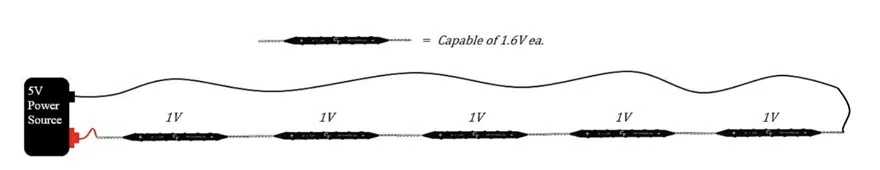
Since many applications operate at a voltage which is higher than what a single cell can handle, CBCs can be connected in series with one another so that the module of CBCs can handle a higher operating voltage. The following formula can be used to determine how many CBC cells need to be connected in series for an application:
Number of Series Connected Cells = Max Operating Voltage / 1.6V
Where 1.6V is the voltage rating of a single CBC cell.
In an ideal CBC module, where each CBC cell has a similar ESR, the overall voltage applied to the CBC module will be equally divided between each cell. This results in a lower voltage applied across each individual CBC. In designing a CBC module, in general, it is a good idea to design the module so that each individual CBC cell is charged to less than their maximum voltage rating. By reducing the voltage applied to each individual CBC cell, the supercapacitors will be safer and have a longer lifecycle since they are not running at maximum capacity continuously.
There is a tradeoff with this approach. While a series connection increases the voltage limit, it decreases the effective capacitance and increases the ESR of the module. Alternatively, a parallel connection will increase the capacitance and decrease the ESR but the voltage rating will remain the same
Since modules are made up of multiple individual cells, the module’s performance is can be described in equivalent units for capacitance, ESR, voltage, etc. The equivalent units are represented as “eq” and are understood to be the value after algebraic modification.
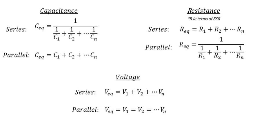
Each unit of the CBC features 3F capacitance, 0.25Ω ESR, and a 1.6V rating. For this reason, these formulas may be simplified as:
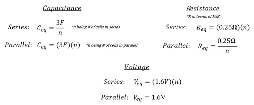
Once a module is formed, the equivalent specifications of the module can be used to calculate power and energy using the same formulas as single cell evaluation.
Using these equations, a variety of supercapacitor modules can be formed with the CBC. For example:
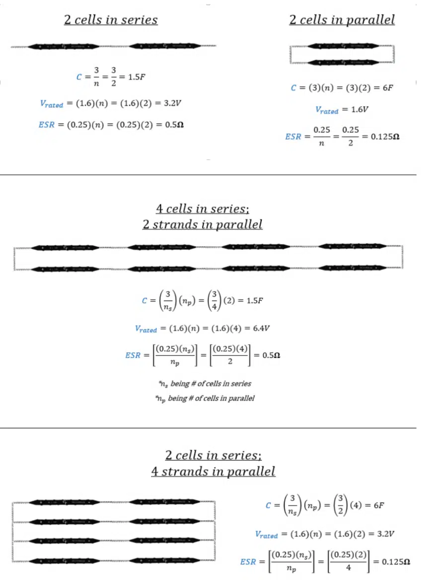
A simplified approach to designing CBC modules is to:
- Understand the max operating voltage of the application
- Calculate the number of cells required in series to meet the voltage requirement
- Understand the goals of the application (general design goals such as energy storage and performance requirements
- Connect cells in parallel to meet that design goal
In the series connections for the CBC modules, a balancing circuit may be considered. While the individual cells of the CBC module can be very close in performance, they are never the exact same, meaning that over time the voltage will deviate slightly from one another. This can create an unbalanced CBC module. While this deviation is small and may not create any issues, a balancing circuit may be necessary for some applications.
We hope this article explained the fundamentals behind designing a flexible supercapacitor module using our CBCs across any project. We are excited to hear about your project and how we may help you build the technologies of the future.
Reading Flexible Supercapacitor Datasheets
Reading Flexible Supercapacitor Datasheets (and why it matters)
Capacitech Energy, Inc was founded to commercialize technologies that enable the future we want to live in. Alongside the University of Central Florida, we developed novel supercapacitor technology built like no supercapacitor before it to optimize designs and unlock performance.
Supercapacitors are a very exciting technology: capable of charging quickly, providing bursts of power, and surviving hundreds of thousands of cycles. Capacitech produces a wire-like and flexible supercapacitor called the Cable-Based Capacitor (CBC). This flexibility gives engineers new design opportunities through a placement advantage that helps them overcome the tradeoffs they typically face. Imagine a future where supercapacitors (energy storage components) are hidden; out of sight and out of mind.
The future is better with flexible supercapacitors. One of the first steps to building that future is helping researchers and engineers understand the CBC and design it into their products. This article is written as an introduction to the CBC’s datasheet.
Introduction to Datasheets:
Datasheets are instruction manuals provided by manufacturers for electronic components to explain what their product does and how to use it correctly. They may seem lengthy and complicated at first, but contain crucial information necessary for proper use and design that mitigate mistakes and risks. The material you will find in a datasheet will contain details such as, but not limited to:
o Typical device performance specifications
o Absolute minimum/maximum requirements and properties
o Testing without compromising the device
o Proposed uses
For the CBC, like other supercapacitors, the pertinent information is voltage rating, capacitance rating, equivalent series resistance (ESR), leakage current, energy storage capacity, peak power capability, and cycle life.
Voltage Rating:
This is the highest voltage that can be continuously applied to the supercapacitor, without failure and/or damage. The voltage rating is determined by the materials used inside the supercapacitor. Exceeding the voltage rating can damage the CBC’s performance, reduce its operating life, or damage its enclosure leading to a leak.
Capacitance Rating:
Capacitance refers to a supercapacitor’s ability to store energy in the form of an electrical charge. Capacitance indicates how much energy the CBC can store and is measured in the unit known as the Farad. The capacitance, energy storage capacity, and other important characteristics of the CBC can be determined by a Galvanostatic Charge/Discharge (GCD) curve. A GCD curve is produced by charging and discharging the CBC with constant current, as shown in the figure.
Capacitance can then be calculated using the results of the GCD curve and the formula i = C dv/dt , which represents the current being equal to the relationship of capacitance and the ratio of change over voltage and change over time.
Equivalent Series Resistance:
Equivalent Series Resistance (ESR) is the internal resistance of a supercapacitor measured in ohms. Its value is inversely proportional to a supercapacitor’s peak power capability. ESR is calculated by analysis of the GCD curve used to calculate capacitance by measuring the instantaneous voltage drop seen when the supercapacitor switches to its discharging cycle.
Leakage Current:
No supercapacitor is ideal. For this reason, when supercapacitors are modeled for real world analysis, two resistors are included: one is in series with the supercapacitor to represent ESR and the other is in parallel with the supercapacitor to represent leakage current. Leakage current can be thought of as the current required to keep the supercapacitor charged. To determine leakage current of a supercapacitor, connect a supercapacitor to a power supply and monitor the current draw over time (at least a few hours), this is the current required to keep the supercapacitor charged representing the leakage current.
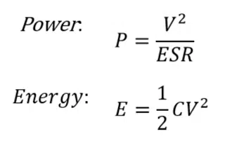
Energy:
The CBC is a supercapacitor, which is an energy storage component at its core. The energy storage capacity of a supercapacitor is calculated by E = 1/2 C V^2 (measured in Joules), proportional to a supercapacitor’s capacitance and the voltage it is charged to (not to exceed its voltage rating). As capacitance and voltage increase, so does the energy storage. This formula can also be used for supercapacitor modules, where supercapacitor cells are connected in series and/or parallel. Supercapacitors are known to have a low energy density, meaning they do not store a lot of energy per unit mass compared to alternatives like batteries and fuel cells. Supercapacitors are not generally used for long-term energy storage needs. U_density = E_max / mass (measured in watt-hours per kilogram).
Power:
Supercapacitors like the CBC are designed for short burst, high-power applications given their high power density. Supercapacitors are designed to respond to sudden fluctuations in power. A supercapacitor’s peak power capability is largely depended on ESR. P_Density = [0.12 * V^2] / [ESR_DC * mass] (measured in watts per kilogram).
Cycle Life:
Although there is a belief that supercapacitors are capable of near infinite cycles in a life, they do have a limit. This idea came from the comparison to batteries, to which supercapacitors are vastly superior in regards to cycle life. The cycle life is the number of times the CBC may be charged and discharged, completing one cycle. To determine cycle life, the CBC is charged to the voltage rating of 1.6V at the current rating of 1.25A and discharge to 0.1V at 1.25A, completing one cycle. The process is repeated again and again until end of life (EOL) capacitance and ESR values are recorded.