Passive Components Blog
No Result
View All Result
  • Home
  • NewsFilter
    • All
    • Aerospace & Defence
    • Antenna
    • Applications
    • Automotive
    • Capacitors
    • Circuit Protection Devices
    • electro-mechanical news
    • Filters
    • Fuses
    • Inductors
    • Industrial
    • Integrated Passives
    • inter-connect news
    • Market & Supply Chain
    • Market Insights
    • Medical
    • Modelling and Simulation
    • New Materials & Supply
    • New Technologies
    • Non-linear Passives
    • Oscillators
    • Passive Sensors News
    • Resistors
    • RF & Microwave
    • Telecommunication
    • Weekly Digest

    Samsung Introduced Low ESL 3-Terminal Reverse-Geometry MLCCs for High-Performance ADAS

    Würth Elektronik Presents New Bidirectional Digital Isolators

    Using Stress–Strain Curves to Diagnose Tantalum Powders for Capacitors

    Coilcraft Introduces SMT Current Sense Transformers for High‑Performance Power Electronics

    Samsung Launches Ultra-Compact 008004 High Q MLCC for Next-Generation RF Applications

    Nichicon Extends Rechargeable Batteries Temperature to Rival Supercapacitors

    Two‑capacitor paradox explained for engineers

    YAGEO Releases Compact RJ45 Connector for Multi‑Gigabit Ethernet

    Circuit Protection Technology Annual Dossier

    Trending Tags

    • Ripple Current
    • RF
    • Leakage Current
    • Tantalum vs Ceramic
    • Snubber
    • Low ESR
    • Feedthrough
    • Derating
    • Dielectric Constant
    • New Products
    • Market Reports
  • VideoFilter
    • All
    • Antenna videos
    • Capacitor videos
    • Circuit Protection Video
    • Filter videos
    • Fuse videos
    • Inductor videos
    • Inter-Connect Video
    • Non-linear passives videos
    • Oscillator videos
    • Passive sensors videos
    • Resistor videos

    Two‑capacitor paradox explained for engineers

    Capacitances of Nonlinear MLCCs: What Datasheets Don’t Tell You

    Tapped Inductor Buck Converter Fundamentals

    Planar vs Conventional Transformer: When it Make Sense

    Modeling Fringing Field Losses in Inductors & Transformers

    Why Power Inductors Use a Ferrite Core With an Air Gap

    Transformer-Based Power-Line Harvester Magnetic Design

    Thermal Modeling of Magnetics

    Standard vs Planar LLC transformers Comparison for Battery Chargers

    Trending Tags

    • Capacitors explained
    • Inductors explained
    • Resistors explained
    • Filters explained
    • Application Video Guidelines
    • EMC
    • New Products
    • Ripple Current
    • Simulation
    • Tantalum vs Ceramic
  • Knowledge Blog
  • DossiersNew
  • Suppliers
    • Who is Who
  • PCNS
    • PCNS 2025
    • PCNS 2023
    • PCNS 2021
    • PCNS 2019
    • PCNS 2017
  • Events
No Result
View All Result
Passive Components Blog
No Result
View All Result

High-Accuracy Current Measurements: Low-Value Resistors

26.6.2017
Reading Time: 3 mins read
A A

source: All about circuits article

If you need high precision in your current measurements, you also need high precision in your current-sense resistor.

RelatedPosts

Samsung Introduced Low ESL 3-Terminal Reverse-Geometry MLCCs for High-Performance ADAS

Würth Elektronik Presents New Bidirectional Digital Isolators

Using Stress–Strain Curves to Diagnose Tantalum Powders for Capacitors

Despite the astonishing advancements in so many aspects of electronics technology, the dominant approach to measuring current is still based, as far as I can tell, on the use of a current-sense resistor. The resistor goes in series with the current-to-be-measured, the resulting voltage drop is proportional to the current, you measure the voltage, you divide by resistance, and you’re done. It’s a conceptually simple technique, but the details can be troublesome.

The “observer effect” tells us that any measurement will alter the state of the thing being measured. The change might be negligible or even undetectable, but it’s always there. So we know that any method of measuring any quantity in a circuit will have some effect on the state of the circuit. Nevertheless, the nature of electricity is such that we can often measure voltage without significantly altering the rest of the circuit. This “measurement-friendly” nature of potential difference makes current measurements look all the worse.


The Trade-Off

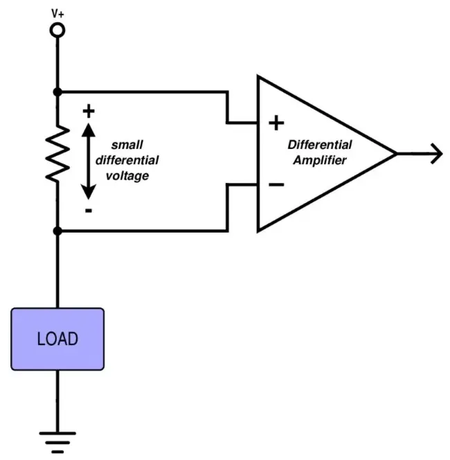
The fact is, the use of a current-sense resistor is an invasive technique. You’re deliberately adding resistance where previously you had only a conductor. Of course you can make the resistance very small, but this is a diminishing-returns situation: Yes, lower resistance is better (to a point), because you have less wasted power and the resistor more closely resembles the effect of a wire or PCB trace. But the whole point here is to generate a voltage that can be measured and converted into current. This voltage will be fed to an amplifier, and amplifiers come with fixed errors, i.e., errors that are not dependent on the amplitude of the input signal. Thus, smaller sense resistance means lower voltage, which means lower signal-to-noise ratio, which means lower accuracy in your current measurement.


Don’t forget to consider the less-effort-required solutions, such as the INA250 from Texas Instruments. It already has a sense resistor and probably works better than anything that I could design.


So as always, everything depends on your requirements and restrictions. You can combine a very-low-value resistor (say, 1 mΩ or less) with a high-precision amplifier and end up with fabulous current measurements and minimal effect on the original circuit. But, you might find that the current-sense circuit costs more than the rest of your device, or you might botch the PCB layout and thereby downgrade your accuracy from “fabulous” to, say, “above average.”


KOA Speer’s Contribution

My instinct tells me that 1 mΩ is a bit extreme for most applications, and that is reflected in the resistance range of KOA Speer’s UR73V2A series of current-sense resistors, which are available from 10 mΩ to 100 mΩ. The power rating is 0.5 W, and the package is 0805.


We often don’t have to worry about power dissipation with very-low-value resistors, but just in case you’re measuring high currents, remember to derate.


I think we all realize that precision is important when you’re choosing a current-sense resistor: you determine current based on the resistance; if the resistance in your calculation is different from the actual resistance, you have error. But another thing to keep in mind is the temperature coefficient.

Like just about everything else in a circuit, resistance is affected by temperature. This means that if your calculation uses a single value for the current-sense resistance, it will always be at least a little bit wrong, unless your device is designed to operate only in a temperature chamber. The easiest way to reduce this wrongness is to choose a resistor with a low temperature coefficient. The UR73V2A series comes with temperature coefficient as low as ±75 ppm/°C. The parts per million thing can be distracting, so let’s take an example.

Your device is sitting next to an oven which is now actively baking some French bread, and the operational temperature eventually increases by 20°C. This corresponds to 75 ppm/°C × 20°C = 1500 ppm, and (1500 ppm)/106 = 0.15%. This higher resistance will create a higher voltage drop, but your code still uses the original resistance, so your calculation will yield a current that is 0.15% higher than the actual current. I don’t know what your requirements are, but I’m guessing that most applications could cope with this sort of error.

Related

Recent Posts

ESA SPCD 26 Registration Open

15.5.2026
24

Stackpole Releases Automotive Wide‑Termination Resistors

14.5.2026
28

Molecular Memristor Shows Record 145 kH Emergent Inductance

12.5.2026
48

Stackpole Expanded its AlN Thick Film Chip Resistors

6.5.2026
27

Modelithics Releases COMPLETE v26.1 for Keysight ADS

23.4.2026
29

April 2026 Interconnect, Passives and Electromechanical Components Market Insights

22.4.2026
160

ECIA March 2026 Industry Pulse Points to Best Sales Climate in Five Years

13.4.2026
96

March 2026 Interconnect, Passives and Electromechanical Components Market Insights

2.4.2026
148

APEC 2026 Power Electronics Trends and Implications for Passive Components

1.4.2026
230

Upcoming Events

Jun 2
16:00 - 17:00 CEST

Calculation, Simulation and Measurement of 800V EMC Filters

Jun 16
16:00 - 17:00 CEST

EMC with EMC – EMC‑compliant design with electromechanical connectors

View Calendar

Popular Posts

  • Buck Converter Design and Calculation

    0 shares
    Share 0 Tweet 0
  • Boost Converter Design and Calculation

    0 shares
    Share 0 Tweet 0
  • Flyback Converter Design and Calculation

    0 shares
    Share 0 Tweet 0
  • LLC Resonant Converter Design and Calculation

    0 shares
    Share 0 Tweet 0
  • MLCC and Ceramic Capacitors

    0 shares
    Share 0 Tweet 0
  • Capacitor Charging and Discharging

    0 shares
    Share 0 Tweet 0
  • What Electronics Engineer Needs to Know About Passive Low Pass Filters

    0 shares
    Share 0 Tweet 0
  • Dual Active Bridge (DAB) Topology

    0 shares
    Share 0 Tweet 0
  • Ripple Current and its Effects on the Performance of Capacitors

    3 shares
    Share 3 Tweet 0
  • Samsung Electro-Mechanics Releases High-Capacitance MLCCs for AI Server Applications

    0 shares
    Share 0 Tweet 0

Newsletter Subscription


Passive Components Blog

© EPCI - Leading Passive Components Educational and Information Site

  • Home
  • Privacy Policy
  • EPCI Membership & Advertisement
  • About

No Result
View All Result
  • Home
  • Knowledge Blog
  • PCNS

© EPCI - Leading Passive Components Educational and Information Site

This website uses cookies. By continuing to use this website you are giving consent to cookies being used. Visit our Privacy and Cookie Policy.
Go to mobile version