• Latest
  • Trending
  • All
  • Capacitors
  • Resistors
  • Inductors
  • Filters
  • Fuses
  • Non-linear Passives
  • Applications
  • Integrated Passives
  • Oscillators
  • Passive Sensors
  • New Technologies
  • Aerospace & Defence
  • Automotive
  • Industrial
  • Market & Supply Chain
  • Medical
  • RF & Microwave
  • Telecommunication

High Voltage Transformer Safety Design Requirements – Case Study

20.2.2023

Practical LLC Transformer Design Methodology

31.3.2023

Practical Measurement of Crystal Circuits

31.3.2023

March 2023 ECIA NA Electronic Components Sales Misses Expectations

31.3.2023

4th PCNS Call for Abstracts Extended !

30.3.2023

Würth Elektronik Presents New Series of DC-Link Film Capacitors

30.3.2023

Vishay Increases Anti-Surge Thick Film 0805 Power Resistor Performance with 0.5 W Power Rating

29.3.2023
  • Home
  • Privacy Policy
  • EPCI Membership & Advertisement
  • About
No Result
View All Result
NEWSLETTER
Passive Components Blog
  • Home
  • NewsFilter
    • All
    • Aerospace & Defence
    • Antenna
    • Applications
    • Automotive
    • Capacitors
    • Circuit Protection Devices
    • Filters
    • Fuses
    • Inductors
    • Industrial
    • Integrated Passives
    • Market & Supply Chain
    • Medical
    • New Materials & Supply
    • New Technologies
    • Non-linear Passives
    • Oscillators
    • Passive Sensors
    • Resistors
    • RF & Microwave
    • Telecommunication

    Practical LLC Transformer Design Methodology

    Practical Measurement of Crystal Circuits

    March 2023 ECIA NA Electronic Components Sales Misses Expectations

    4th PCNS Call for Abstracts Extended !

    Würth Elektronik Presents New Series of DC-Link Film Capacitors

    Vishay Increases Anti-Surge Thick Film 0805 Power Resistor Performance with 0.5 W Power Rating

    Q&A Update on Aluminum Capacitor Technology with Industry Highest Energy Density >5J/cc Available for Acquisition

    Designing with High Voltage Resistors: 10 Top Tips for Success

    API Delevan Introduces 0402 and 0603 Small High Reliability Space SMD Inductors

    Trending Tags

    • Ripple Current
    • RF
    • Leakage Current
    • Tantalum vs Ceramic
    • Snubber
    • Low ESR
    • Feedthrough
    • Derating
    • Dielectric Constant
    • New Products
    • Market Reports
  • VideoFilter
    • All
    • Antenna videos
    • Capacitor videos
    • Filter videos
    • Fuse videos
    • Inductor videos
    • Non-linear passives videos
    • Oscillator videos
    • Passive sensors videos
    • Resistor videos
    • Sensors

    Practical LLC Transformer Design Methodology

    Practical Measurement of Crystal Circuits

    Investigating Modeling Techniques of Class II Ceramic Capacitors Losses for High Voltage and Current Applications

    Understanding Basics of Current Sense Resistors

    What Decoupling Capacitor Value To Use And Where To Place Them

    How to Measure Rated Current on Power Inductors

    LTspice Simulation of a Spark-Gap Circuit Protection Surge Arrester

    Approximate Inductor Design Using Two Alternative Cores

    1kW Phase Shift Full Bridge Converter Design and Simulation

    Trending Tags

    • Capacitors explained
    • Inductors explained
    • Resistors explained
    • Filters explained
    • Application Video Guidelines
    • EMC
    • New Products
    • Ripple Current
    • Simulation
    • Tantalum vs Ceramic
  • Knowledge Blog
  • Suppliers
    • Preferred Suppliers
    • Who is Who
  • Events
No Result
View All Result
Passive Components Blog
No Result
View All Result

High Voltage Transformer Safety Design Requirements – Case Study

20.2.2023
Reading Time: 7 mins read
0 0
0
SHARES
66
VIEWS

This Frenetic blog article from Sotiris Zorbas, MSc, Power Εlectronics Εngineer at Frenetic provides case study about 450V/12V flyback 10W transformer design to meet isolation and safety requirements.

The task is how to select the appropriate distances in a transformer design and decide exactly how much creepage and clearance is needed for the flyback design.

RelatedPosts

Practical LLC Transformer Design Methodology

Optimization of 500W LLC Transformer – Case Study

Frenetic Announces New CTO of Magnetics

Lets explain the safety and isolation requirement on a 10W flyback transformer design for an auxiliary psu.

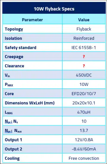
The input voltage in our case study will be 450V and the output 12/8.4V. This case study shares aspects of the actual design, starting with the spec sheet shown in Table 1.

Table 1. Generic 10W auxiliary PSU design flyback transformer specification for the case study
Figure 1. 3D render of the 10W flyback transformer

Insulation Type Selection

The main insulation categories are

  • functional
  • basic
  • reinforced (or double) insulation.

Functional insulation only accounts for a bare minimum insulation that can only guaranty functionality of the transformer. Basic insulation provides protection against fault conditions, such as overvoltage conditions at the primary transformer side. Reinforced isolation is the strictest option, providing maximum protection against fault conditions, making sure that isolation doesn’t break down from the primary to the secondary side.

For this design reinforced isolation was chosen.

Working Voltage

That is the maximum voltage that the insulation of the transformer can experience under normal operating conditions. In our case that’s about 450V between the primary winding and the secondaries.

Pollution Degree

The standard specifies different pollution degrees depending on the actual machine/product the transformer is used in. For example an epoxy potted transformer will always be clean, away from humidity and dust. But the most common thing is unpotted transformers that are subjected to dust humidity and other “pollutants”.

IEC 61558-1 defines pollution degree as below:

  • Pollution degree 1: “Pollution degree in which no pollution or only dry, non-conductive pollution occurs.”
  • Pollution degree 2: “pollution degree in which only non-conductive pollution occurs, except that occasionally a temporary conductivity caused by condensation is to be expected.”
  • Pollution degree 3: “pollution degree in which conductive pollution occurs, or dry non-conductive pollution occurs which becomes conductive due to the condensation which is to be expected.”

Most times pollution degree 2 is chosen, as is the case with this design as well.

Overvoltage Category

That is a probabilistic categorization that hasn’t got to do with the transient voltages that a transformer will experience necessarily, but it’s rather a categorization depending on the application the transformer is used in.

We have 4 overvoltage categories (OVCs) named I to IV. Take a look at Table 2 to understand the applications and description of each overvoltage category.

Table 2. OVCs as described in IEC61558-1

Overvoltage category II was appropriate here.

CTI Index

Table 3. CTI-material group category based on Annex G of IEC 61558-1

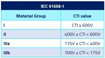
CTI index is the voltage which causes tracking after 50 drops of 0.1% ammonium chloride solution have fallen on the material.

The results of testing at 3 mm thickness are considered representative of the material’s performance in any thickness. Tracking is the breakdown of insulation on top of an insulator created from a voltage potential which gradually creates a carbonized conductive path along the surface, creating a leakage-conductive path.

When we talk about insulating materials we consider the bobbin, insulating tape between layers, margin tape and wire ending sheeves like heat shrink tubes.

The cost effective/good compromise is to select material group II (400V ≤ CTI < 600V ) for all of the aforementioned components.

Finding the Minimum Clearance Distance

We have previously selected:

  • OVC II
  • Reinforced isolation
  • Pollution degree 2
  • Working voltage 450V

From IEC61558-1 in Table 4 we see that the necessary clearance is between 3-5.5mm. Although most standards allow linear interpolation between values in tables, for this table the standard forbids this. So the minimum clearance is 5.5mm.

Table 4. IEC 61558-1 clearance selection table

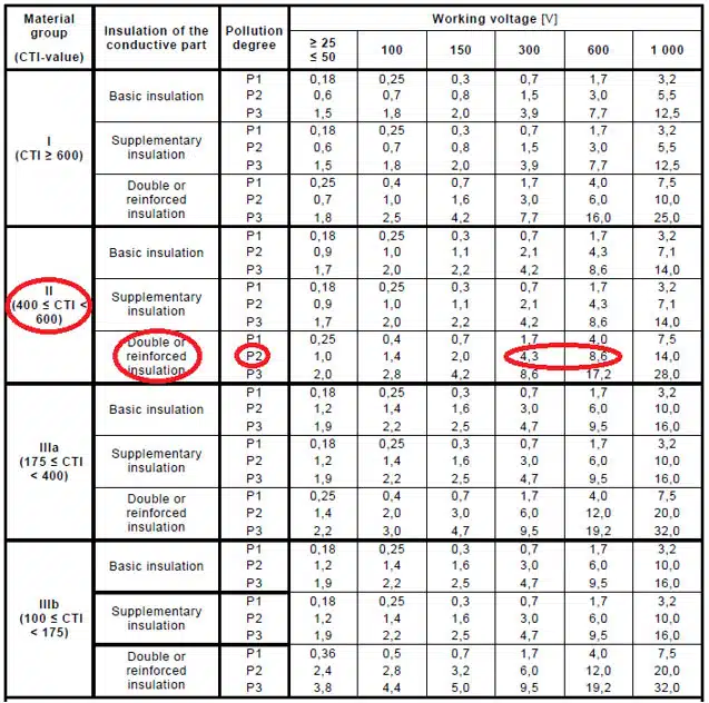
Finding the Minimum Creepage Distance

We have previously selected:

  • Material category II
  • Reinforced isolation
  • Pollution degree 2
  • Working voltage 450V

From IEC61558-1 in Table 5 the necessary creepage is between 4.3-8.6mm. In this case linear interpolation between table values is permitted, thus 6.5mm of creepage distance is calculated for 450V.

Table 5. IEC 61558-1 creepage selection table

Margin Tape and Windings Picture

This design was built with margin tape. Using 3.5mm of margin tape on each layer the final creepage is set at 3.5×2=7mm, as shown in Figure 2.

Figure 2. Margin tape of the 10W flyback transformer

Summary

Now you’re in the position to understand in more detail the way we comply with a safety standard. To be honest there are a lot more things that need to be taken care of to make sure the transformer complies, but this is a mayor step in this direction.

References

  1. (2018) Transformer Design Considerations. tech. Wurth Electronik. (Accessed: February 13, 2023).
  2. IEC 61558-1, Safety of transformers, reactors, power supply units and combinations thereof. part 1, General Requirements and tests (IEC 61558-1:2017) (2019).
Source: Frenetic

Related Posts

Inductors

Practical LLC Transformer Design Methodology

31.3.2023
2
Oscillators

Practical Measurement of Crystal Circuits

31.3.2023
3
Market & Supply Chain

March 2023 ECIA NA Electronic Components Sales Misses Expectations

31.3.2023
2

Upcoming Events

Apr 3
April 3 @ 12:00 - April 4 @ 14:00 CEST

Microelectronic Packaging Failure Modes and Analysis

Apr 5
11:00 - 12:00 CEST

Plugging – Filling – Tenting; WE PCB Webinar

Apr 6
April 6 @ 12:00 - April 7 @ 14:00 EDT

Space and Military Standards for Hybrids and RF Microwave Modules

View Calendar

Popular Posts

  • What is a Dielectric Constant of Plastic Materials ?

    4 shares
    Share 4 Tweet 0
  • Ripple Current and its Effects on the Performance of Capacitors

    3 shares
    Share 3 Tweet 0
  • Capacitor Selection for Coupling and Decoupling Applications

    28 shares
    Share 28 Tweet 0
  • Why Low ESR Matters in Capacitor Design

    0 shares
    Share 0 Tweet 0
  • Leakage Current Characteristics of Capacitors

    0 shares
    Share 0 Tweet 0
  • Capacitor Losses (ESR, IMP, DF, Q), Series or Parallel Eq. Circuit ?

    0 shares
    Share 0 Tweet 0
  • How to Choose the Right Inductor for DC-DC Buck Applications

    0 shares
    Share 0 Tweet 0
  • Understanding High-Precision Resistor Temperature Coefficient of Resistance

    0 shares
    Share 0 Tweet 0

Newsletter Subscription


PCNS Call for Papers !

Archive

2022
2021
2020
2019
2018
2017

Symposium

Passive Components Networking Symposium

Passives e-Learning

Knowledge Blog

  • Home
  • Privacy Policy
  • EPCI Membership & Advertisement
  • About

© EPCI - Premium Passive Components Educational and Information Site

No Result
View All Result
  • Home
  • News
  • Video
  • Knowledge Blog
  • Preferred Suppliers
  • Events

© EPCI - Premium Passive Components Educational and Information Site

Welcome Back!

Login to your account below

Forgotten Password?

Retrieve your password

Please enter your username or email address to reset your password.

Log In
This website uses cookies. By continuing to use this website you are giving consent to cookies being used. Visit our Privacy and Cookie Policy.