Passive Components Blog
No Result
View All Result
  • Home
  • NewsFilter
    • All
    • Aerospace & Defence
    • Antenna
    • Applications
    • Automotive
    • Capacitors
    • Circuit Protection Devices
    • electro-mechanical news
    • Filters
    • Fuses
    • Inductors
    • Industrial
    • Integrated Passives
    • inter-connect news
    • Market & Supply Chain
    • Market Insights
    • Medical
    • Modelling and Simulation
    • New Materials & Supply
    • New Technologies
    • Non-linear Passives
    • Oscillators
    • Passive Sensors News
    • Resistors
    • RF & Microwave
    • Telecommunication
    • Weekly Digest

    Bourns Completes Rakon Acquisition, Enters Timing Market

    Knowles Releases 3825 X1/Y2 Safety MLCCs for High‑Voltage Applications

    Knowles Expands High Q Ceramic Core Inductors

    TAIYO YUDEN Releases 220uF 1210 Automotive MLCC

    HEICO’s Exxelia Expands High-Voltage Ceramic Capacitor Portfolio with CalRamic Acquisition

    Vishay Extends Automotive Ferrite Beads for High‑Current EMC Noise Filtering

    CapXon Earns EcoVadis Bronze Medal for Sustainability Performance

    All‑Water Supercapacitor Based on 1‑nm Clay Channels and Nanoconfined Water Electrolyte

    Littelfuse Unveils High‑Current 48V SMD Fuse for AI Data Center Protection

    Trending Tags

    • Ripple Current
    • RF
    • Leakage Current
    • Tantalum vs Ceramic
    • Snubber
    • Low ESR
    • Feedthrough
    • Derating
    • Dielectric Constant
    • New Products
    • Market Reports
  • VideoFilter
    • All
    • Antenna videos
    • Capacitor videos
    • Circuit Protection Video
    • Filter videos
    • Fuse videos
    • Inductor videos
    • Inter-Connect Video
    • Non-linear passives videos
    • Oscillator videos
    • Passive sensors videos
    • Resistor videos

    Why Isolated DC/DC Power Supplies Fail Late, Würth Elektronik Podcast

    Designing 800 V DC EMC Filters: Calculation, Simulation and Measurement

    Current Sense Transformer Datasheet and Design‑in Guide

    Designing a USB Type‑C Flyback Planar Transformer with Frenetic’s Planar Tool

    Magnetics Design in High‑Frequency GaN Converters

    Qi2 Wireless Charging: Inductors, Capacitors and EMC Filters

    Two‑capacitor paradox explained for engineers

    Capacitances of Nonlinear MLCCs: What Datasheets Don’t Tell You

    Tapped Inductor Buck Converter Fundamentals

    Trending Tags

    • Capacitors explained
    • Inductors explained
    • Resistors explained
    • Filters explained
    • Application Video Guidelines
    • EMC
    • New Products
    • Ripple Current
    • Simulation
    • Tantalum vs Ceramic
  • Knowledge Blog
  • DossiersNew
  • Suppliers
    • Who is Who
  • PCNS
    • PCNS 2025
    • PCNS 2023
    • PCNS 2021
    • PCNS 2019
    • PCNS 2017
  • Events
No Result
View All Result
Passive Components Blog
No Result
View All Result

Insertion Loss and Performance in EMI Filtering

23.2.2022
Reading Time: 4 mins read
A A

KnowlesCapacitors blog explains insertion loss and performance in EMI filtering in article by Peter Mathews.

To comply with international legislation such as the EU Directive on EMC or the FCC, EMI filtering is an essential element of equipment design. Here, we will continue to explore EMI filtering through insertion loss and filtering performance.

RelatedPosts

Knowles Releases 3825 X1/Y2 Safety MLCCs for High‑Voltage Applications

Knowles Expands High Q Ceramic Core Inductors

Knowles Doubles Capacitance of its Class I Ceramic C0G Capacitors

The insertion loss performance shows signal attenuation at any given frequency. As a metric, the insertion loss performance is most useful as a guide in the filter selection process; the actual performance in service can vary depending on circuit characteristics.

Insertion loss is determined by the following factors:

  • Electrical configuration
  • Source/load impedances
  • Load current
  • Ceramic dielectric materials
  • Earthing impedance
  • Shielding integrity

Electrical Configuration

The choice of electrical configuration for a filter (the capacitor/inductor combination) primarily depends on the source and load impedances. Insertion loss figures are normally published for a 50Ω source and 50Ω load circuit. Impedance, in reality, will probably be different than the figures imply and could cause an increase or decrease in insertion loss. The electrical configuration of the filter should be chosen to optimize the filter performance for a specific source/load impedance scenario.

Common types of electrical configurations available in feedthrough filters include:

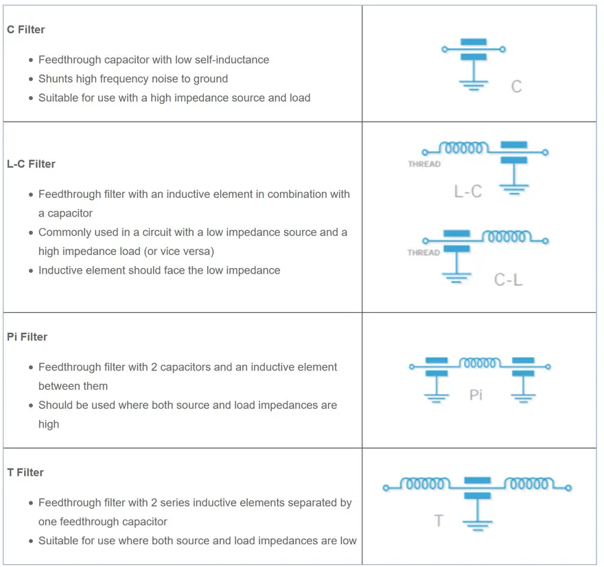
Multi-Element Filter

Contains more than 3 elements, for example L-C-L-C-L filters (addition of further elements increases the steepness of the insertion loss curve)

Load Current

The effect of load current on insertion loss is largely determined by the properties of the filtering elements used. For filtering circuits with inductive elements, insertion loss might experience a significant reduction where ferrite inductors are used; ferrite material saturates with current. Reduction in insertion loss depends on the current and the characteristics of the particular ferrite material. In extreme cases, the ferrite will become ineffective and insertion loss will appear to be the same as for a C filter.
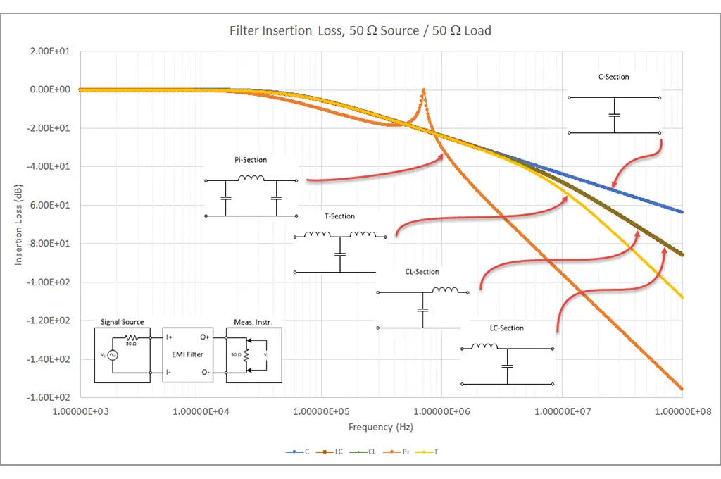
Choosing a Filter

When selecting a filter, electrical configuration, physical implementation, and material (i.e. dielectric type) are all important considerations. The attenuation curve, shown in Figure 1, charts the various physical implementations of the electrical configurations detailed above. You’ll notice a simple chip filter provides the least attenuation at high frequency. Looking at either of these characteristics individually could be misleading in your selection process.

Figure 1: Attenuation Curve – A plot of insertion loss versus frequency on a logarithmic scale; source: S.Nelson, Medium

Looking, again, at the component itself, different categories of ceramic materials have different performance characteristics. For instance, as the dielectric constant increases (and therefore filter capacitance value increases), stability deteriorates. Specific operational and environmental parameters—including temperature, voltage, frequency, and time (aging)—can affect the dielectric constant.

Figure 2: Summary table of ceramic dielectric characteristics

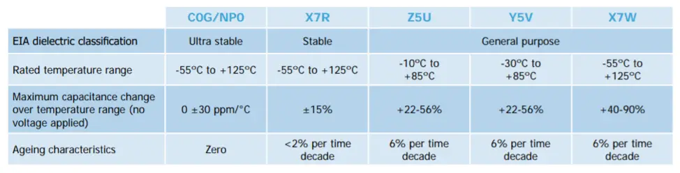
As summarized in Figure 2, the three main classifications of ceramic dielectric employed in the manufacture of EMI filters are generally referred to as ultra stable (C0G/NP0), stable (X7R) and general purpose (Z5U, Y5V or X7W).

C0G/NP0 – Ultra Stable Most material parameters remain unaffected by temperature, voltage, frequency or time Stabilities are measured in terms of parts per million but dielectric constants are relatively low (10 to 100)
X7R – Stable Material parameters are relatively stable with respect to temperature, voltage, frequency and time Typical dielectric constants would be of the order 2,000 to 4,000, enabling far higher capacitance values for a given size of capacitor than can be gained from C0G/NP0 materials If the voltage coefficient (VC) is critical, Knowles Precision Devices can also support parts with BX (2X1) and BZ (2C1) VC characteristics
Z5U/Y5V/X7W – General Purpose Material parameters are severely restricted and performance under applied voltage may be seriously compromised Note: Knowles Precision Devices uses only the higher performance C0G/NP0 and X7R in its standard ranges

Spread of Capacitance Values

The capacitance of a ceramic capacitor also changes as a result of varying temperature, applied voltage, and age. The final capacitance can fall within a range of values depending on material type and characteristics referenced in Figure 2. That said, if capacitance has reduced, so will the insertion loss performance.

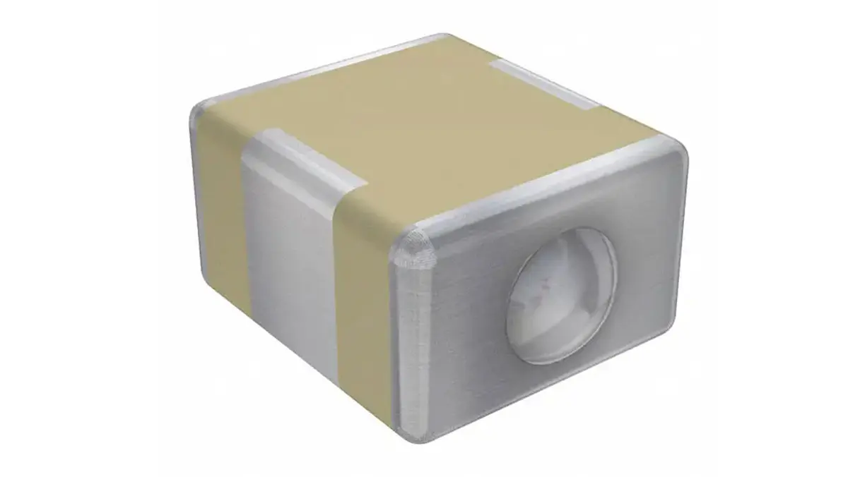
featured image source: KnowlesCapacitors feedthrough

Related

Source: KnowlesCapacitors blog

Recent Posts

Knowles Releases 3825 X1/Y2 Safety MLCCs for High‑Voltage Applications

11.6.2026
27

Knowles Expands High Q Ceramic Core Inductors

11.6.2026
19

TAIYO YUDEN Releases 220uF 1210 Automotive MLCC

11.6.2026
37

HEICO’s Exxelia Expands High-Voltage Ceramic Capacitor Portfolio with CalRamic Acquisition

10.6.2026
36

Vishay Extends Automotive Ferrite Beads for High‑Current EMC Noise Filtering

10.6.2026
26

CapXon Earns EcoVadis Bronze Medal for Sustainability Performance

10.6.2026
24

All‑Water Supercapacitor Based on 1‑nm Clay Channels and Nanoconfined Water Electrolyte

10.6.2026
35

Modelithics Releases COMPLETE Library v26.2 for Keysight Genesys

8.6.2026
21

Why Isolated DC/DC Power Supplies Fail Late, Würth Elektronik Podcast

8.6.2026
44

Upcoming Events

Jun 16
16:00 - 17:00 CEST

EMC with EMC – EMC‑compliant design with electromechanical connectors

Jul 14
16:00 - 17:00 CEST

EMC Design Essentials: Mastering Varistors and Common Mode Chokes

Jul 21
16:00 - 17:00 CEST

Safety by design: X and Y Interference suppression capacitors for power line filters

View Calendar

Popular Posts

  • Buck Converter Design and Calculation

    0 shares
    Share 0 Tweet 0
  • Boost Converter Design and Calculation

    0 shares
    Share 0 Tweet 0
  • LLC Resonant Converter Design and Calculation

    0 shares
    Share 0 Tweet 0
  • MLCC and Ceramic Capacitors

    0 shares
    Share 0 Tweet 0
  • Flyback Converter Design and Calculation

    0 shares
    Share 0 Tweet 0
  • SEPIC Converter Design and Calculation

    0 shares
    Share 0 Tweet 0
  • Earthing Systems and IEC Classification Explained

    0 shares
    Share 0 Tweet 0
  • Dual Active Bridge (DAB) Topology

    0 shares
    Share 0 Tweet 0
  • What Electronics Engineer Needs to Know About Passive Low Pass Filters

    0 shares
    Share 0 Tweet 0
  • MLCC Case Sizes Standards Explained

    0 shares
    Share 0 Tweet 0

Newsletter Subscription


Passive Components Blog

© EPCI - Leading Passive Components Educational and Information Site

  • Home
  • Privacy Policy
  • EPCI Membership & Advertisement
  • About

No Result
View All Result
  • Home
  • Knowledge Blog
  • Dossiers
  • PCNS

© EPCI - Leading Passive Components Educational and Information Site

This website uses cookies. By continuing to use this website you are giving consent to cookies being used. Visit our Privacy and Cookie Policy.
Go to mobile version